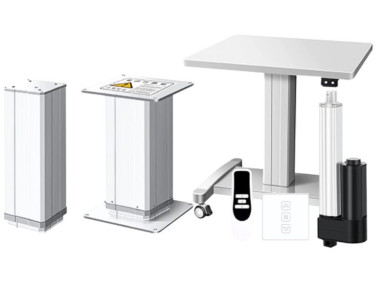
Опасность боковых нагрузок на линейные актуаторы: Как предотвратить механическую поломку
Предотвратите преждевременный механический сбой в ваших линейных системах. Этот экспертный гид объясняет физику «боковых нагрузок» и «статических изгибающих моментов», подробно рассматривая, как боковые силы повреждают внутренние подшипники и винты, и предоставляет 5 основных практик установки для продления срока службы ваших актюаторов.
Learn how side loads and bending moments affect linear-actuator installations, and how to verify alignment, guides, brackets and selected-model limits before approval.
Содержание
Введение
Unexpected noise, vibration, current increase or wear can have several causes, including misalignment, binding, unsupported side load, mounting looseness or internal wear. Diagnose the complete mechanism rather than assigning the symptom to side load by default.
Some actuator specifications state that side loads are not permitted or give a maximum lateral load / bending-moment limit. Apply the exact wording, reference point and limit from the selected model’s current drawing or specification rather than treating one warning as universal.
A side load acts across the actuator’s primary motion axis and can create bending moment, guide/bearing load, seal load, friction or structural stress. The effect depends on the actuator design, mounting geometry, lever arm, external guidance and the selected model’s allowable lateral-load / moment limits.
This guide explains side load and bending moment, then shows how to review load path, mounting, articulation and external guidance for линейный актуатор projects. The goal is to keep the finished mechanism within the selected actuator’s documented limits, not to promise that all side-load risk can be eliminated.
Понимание боковых нагрузок: Инженерные основы
Что такое боковая нагрузка?
A боковая нагрузка (lateral load) is a force component acting perpendicular to the actuator’s primary motion axis. Axial-force and allowable lateral-load / bending-moment ratings are model-specific; some actuators permit very little side load, while others publish a defined limit or require external guidance.
An angled or offset force can create both a lateral force component and a изгибающий момент. The actual moment depends on force magnitude, direction and lever arm relative to the relevant support or mounting reference.
Что такое статический изгибающий момент?
Термин статический изгибающий момент относится к вращательной силе, создаваемой, когда боковая нагрузка прикладывается на расстоянии от контрольной точки (в данном случае монтажного фланца актюатора). Математически это вычисляется как:
Изгибающий момент = Сила × Расстояние
Even a modest lateral force can create a meaningful moment when the lever arm is long. For example, 50N applied 100mm (0.1m) from the reference point creates 5Nm. Whether 5Nm is acceptable must be checked against the selected actuator / mounting system’s allowable moment and test conditions.
If a selected model states “side loads are not permitted,” treat that as a product-specific design constraint and provide external guidance or a mounting arrangement that keeps lateral load off the actuator. If a model publishes a nonzero side-load / bending-moment limit, use that documented limit and reference geometry. Exceeding the applicable limit can contribute to:
Bearing / guide wear: unsupported lateral or moment load can change internal contact loading and increase wear
Screw / nut stress: misalignment or side load can increase friction or uneven contact in screw-driven mechanisms
Structural stress: housings, rods, mounts or fasteners can see additional bending stress depending on the load path
Current / thermal change: binding or extra friction can increase motor current and heat, depending on the motor/controller and load
Почему боковые нагрузки вызывают повреждения: Более детальный взгляд на механику
Проблема с неправильным выравниванием
Когда линейный актуатор работает в условиях боковой нагрузки, внутри устройства происходит несколько вещей:
Bearing / guide loading: off-axis force can change contact loading and may increase wear if the selected mechanism is not rated for it.
Напряжение в винтовом механизме: in screw-driven actuators, misalignment can increase uneven contact, friction or load on the screw/nut/guide system.
Seal / rod loading: rod deflection or misalignment can change seal contact and wear; the effect depends on the rod, guide and sealing design.
Current / friction increase: binding can raise required force and motor current; verify with the selected actuator/controller data rather than assuming a fixed efficiency loss.
Последствия в реальном мире
As an illustrative case, consider a mechanism using a heavy-duty actuator where the moving structure is not adequately guided and the actuator is forced to react an offset load. The resulting side load or bending moment depends on the real geometry, load and support arrangement.
Possible symptoms—none unique to side load—can include:
Необычный шум во время работы
Трясущиеся или нереговные движения
Увеличение потребления энергии
Mechanical damage or loss of function if the underlying condition is severe or left uncorrected
The risk can often be reduced by designing the load path, external guidance, mounts and articulation around the selected actuator’s limits, then validating the finished mechanism under representative load and travel.
Как предотвратить повреждение от боковой нагрузки: Лучшие практики установки
Side-load control is a system-design task involving actuator selection, load path, external guidance, mounting geometry, assembly tolerance and validation. Use the following items as review checkpoints:
1. Verify Load-Path Alignment
Keep the actuator within its documented alignment, side-load and bending-moment limits throughout full travel. In mechanisms that intentionally rotate or change angle, the mounts and pivots must allow the required articulation without forcing the actuator to act as an unintended guide.
Use mounting hardware and interface dimensions appropriate to the selected actuator and load geometry
Check the actual load path, parallelism / articulation and binding through full travel using suitable measurement methods
Account for frame deflection, manufacturing tolerance and thermal movement where they can alter alignment
2. Используйте правильные монтажные кронштейны
Use кронштейны и крепления whose hole pattern, pin/clevis geometry, articulation, material and load rating are appropriate for the selected actuator and mechanism. Confirm the actual bracket configuration rather than assuming a generic bracket solves misalignment.
For the selected mounting arrangement, verify:
Correct interface, pin/fastener fit and supported load path
Required articulation or bearing/rod-end function where the mechanism changes angle
Load transfer into the intended mounting points without unintended side loading of the rod or housing
3. Правильно поддерживайте нагрузку
Если ваше приложение включает любые боковые перемещения или если нагрузка имеет массу, которая может создавать боковые силы, включите дополнительные механизмы направляющей:
External linear rails, guide shafts or another structure sized to react lateral/moment loads where required
Pivot / clevis / rod-end mounts where the mechanism requires angular articulation and the selected actuator permits that arrangement
Separate environmental covers or guards when contamination protection is required; do not treat a cover as a lateral-load guide
4. Учитывайте силы, действующие под углом к оси
Where the mechanism includes angular motion, tolerance or unavoidable offset, evaluate suitable articulation and guidance rather than relying on the actuator to absorb the mismatch:
Rod-end / spherical bearings: may allow angular articulation when correctly sized and approved for the load
Поворотные крепления: can be appropriate for changing-angle mechanisms when the selected actuator, pins and brackets are rated for the load path
Flexible interfaces / couplings: use only where the mechanical architecture calls for them; they are not a substitute for adequate guidance or correct geometry
5. Регулярная проверка и обслуживание
After installation and validation, inspect at the interval defined by the equipment maintenance plan and actual service conditions for:
Освобожденного монтажного оборудования (вибрация может вызвать ослабление крепежа)
Признаков необычного износа
Изменений в звуке или производительности, которые могут указывать на возникающие проблемы
Выбор правильных компонентов для вашего применения
При выборе линейных актуаторов для вашего проекта учитывайте конкретные требования к установке:
Требования к применению
Фактор
Engineering check
Величина нагрузки
Calculate axial, lateral, moment, static/dynamic and holding loads; apply the safety factor required by the equipment design or applicable standard rather than a universal 2–3× rule
Stroke / geometry
Confirm stroke, retracted/extended dimensions, mounting points and lever arms through full travel
Speed / motion
Confirm speed, acceleration, load path and dynamic effects for the selected actuator/controller configuration
Рабочий цикл
Use the selected product’s duty/thermal limits and actual motion profile; do not infer side-load capacity from duty rating
Окружение
Confirm enclosure, corrosion, contamination, temperature and maintenance requirements separately from mechanical load capacity
В случае сомнений проконсультируйтесь с экспертами
For complex промышленная автоматизация mechanisms, provide drawings, load cases, motion path, mounting geometry, duty cycle and environmental requirements so candidate actuators, guides and mounts can be compared against current specifications before approval.
For the electrical side, confirm the selected control box / controller, current limits, feedback, end limits and fault behavior as part of the complete mechanism review.
Могу ли я использовать линейный актюатор для поддержки тяжелой двери, открывающейся под углом?
Possibly, but the mechanism must be analyzed through the full motion range. A pivot, clevis or rod-end bearing may allow required articulation, while separate hinges/guides may need to react lateral and moment loads. Confirm actuator force, mounting-pin loads, side-load/bending-moment limits, geometry and stability for the selected design.
Какой самый распространенный признак повреждения от боковой нагрузки?
There is no single diagnostic symptom. Unexpected noise, jerky motion, higher current, rod or guide wear, seal wear, fastener movement or changing alignment can have multiple causes. Stop and inspect the complete load path, guidance, mounting and actuator condition against the selected documentation.
Как линейные рельсы помогают предотвратить боковые нагрузки?
A correctly sized and aligned external guide can be designed to react some or most lateral and moment loads so the actuator primarily provides axial force. Actual load sharing depends on rail spacing, stiffness, tolerances, mounting and mechanism geometry; verify it analytically and on the finished assembly.
Conclusion: Validate Load Path & Side-Load Limits
Side load and bending moment should be treated as explicit mechanical design inputs. If the selected actuator states that side loads are not permitted, design the mechanism so external structure/guides react them. If a lateral-load or moment rating is published, keep the complete load case within that defined limit and reference geometry.
Use these controls to reduce side-load risk and validate the mechanism:
Design the load path: keep actuator loading within the selected model’s axial, lateral and moment limits throughout travel
Verify mounts / guides: confirm кронштейны и крепления, pins, bearings and external guides for the actual geometry and loads
Use current documentation: apply the selected actuator’s drawings, side-load / bending-moment limits, installation requirements and maintenance instructions
Inspect by maintenance plan: monitor alignment, fasteners, guides, abnormal noise/current and wear at intervals appropriate to the finished equipment
Controlling side load and bending moment can reduce avoidable mechanical stress, but service life and downtime depend on the selected actuator, load spectrum, duty cycle, environment, controls, maintenance and complete machine design.
Treat the actuator as one element of the motion system: give lateral/moment loads to the structures intended to carry them, confirm articulation and guides, and validate the selected actuator under representative operating conditions.
For project review, use the линейный актуатор, heavy-duty actuator и standing desk frame categories to identify candidates, then confirm the selected model’s load, moment, mounting and guidance requirements before approval.
For configuration review, provide a mechanism drawing, load cases, mounting points, full-travel geometry, duty cycle and environmental conditions.
Sources & Evidence Boundary
Primary product evidence: the selected actuator’s current drawing/specification, including allowable side load / bending moment, mounting reference points and installation limits.
Получите экспертные рекомендации по промышленному управлению движением
Выбор правильного электрического линейного актуатора или подъемную колонну критически важен для производительности вашего проекта. Как профессиональный Производитель управления движением и автоматизации, наши инженеры помогут вам настроить грузоподъемность, длину хода и рейтинги IP в зависимости от ваших конкретных приложений. Поделитесь своими техническими требованиями для индивидуального решения.
ActuLift поддерживает полную индивидуализацию, от структурного проектирования и параметров хода до брендинга и отделки корпусов, помогая вам создать мощную идентичность бренда.
Быстрый ответ и прототипирование
Мы понимаем важность скорости в B2B закупках, используя оптимизированные производственные потоки для обеспечения эффективных ответов от разработки образцов до массовых поставок.
Quality Documentation & Traceability
Quality and traceability requirements vary by project. Ask ActuLift for the applicable inspection records, product specifications, drawings and available compliance documentation for the selected model and order.