Почему сила самозакрытия важна в приложениях вертикального подъема
Узнайте, как сила самозакрытия актуатора помогает противостоять обратному движению в вертикальных подъемных системах и что инженеры OEM должны проверять за пределами динамической грузоподъемности.
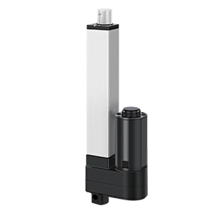
Когда электрический линейный актуатор электрическим подъемным столбом движется, мотор и трансмиссия генерируют силу, необходимую для подъема или опускания нагрузки. Но что происходит, когда движение останавливается?
Еще более важно, что происходит, когда питание отключается?
В горизонтальном приложении небольшое количество обратного движения может вызвать нежелательное дрейфование положения. В вертикальном приложении подъема гравитация постоянно действует на механизм. Если актуатор не может противостоять этой силе, платформа, экран, рабочая поверхность, крышка, медицинский компонент или сборка машины могут медленно опуститься — или двигаться гораздо быстрее, чем ожидалось.
Вот почему сила самозакрытия, также описанная в некоторых спецификациях как статическая удерживающая сила или статическая демпфирующая сила, заслуживает своего места в процессе выбора.
Она отвечает на вопрос, на который динамическая грузоподъемность не дает полного ответа:
Сколько осевой нагрузки выбранная конфигурация актуатора может выдержать, оставаясь неподвижной и без питания, без того, чтобы внешний груз заставлял винт или трансмиссию обратным движением?
Для инженеров OEM и команд закупок важный урок прост: актуатор, который может поднимать нагрузку под напряжением, не обязательно доказан как безопасный для удержания той же нагрузки в каждом остановленном, без питание или аномальном состоянии.
Содержание
Что такое сила самозакрытия?
Сила самозакрытия — это осевая нагрузка, которую непитаемый актуатор может выдержать, не позволяя внешней нагрузке вызывать обратное движение винта или трансмиссии.
Обратное движение происходит, когда груз заставляет механизм двигаться назад. В вертикальной системе гравитация может толкать или тянуть шток актуатора, вращать винт через гайку и двигать нагрузку вниз, даже если мотор больше не питается.
Упрощенная механика самозакрытия винта
Для винтового механизма первая теоретическая проверка сравнивает угол винтовой подачи, α, с углом трения, ρ. Угол подачи на среднем диаметре винта можно аппроксимировать как:
tan α = подача / (π × средний диаметр винта)
Для идеальной квадратной резьбы упрощенное условие самозаклинивания следующее:
α < ρ или tan α < μs
где μs является статическим коэффициентом трения между винтом и гайкой в момент начала движения. Если угол подачи превышает угол трения, осевая нагрузка может создать достаточно обратного момента, чтобы повернуть винт, поэтому механизм становится обратно приводимым в идеализированной модели. Это помогает объяснить, почему большая подача винта может увеличить перемещение за один оборот — и скорость — но уменьшить естественное сопротивление обратному приводу.
Реальные трапециевидные резьбы требуют более полного расчета. Их угол скоса увеличивает эффективный коэффициент трения, поэтому инженеры обычно сравнивают угол подачи с эффективным углом трения, ρ′, вместо того чтобы использовать уравнение для квадратной резьбы без коррекции. Распространенное упрощенное решение для симметричной трапециевидной резьбы с углом поперечной плоскости β использует μ′ ≈ μs / cos β и ρ′ = arctan μ′. Эффективность редуктора, трение подшипников, материалы винта и гайки, смазка, допуски на изготовление, износ, температура, вибрация и внешнее усилие также влияют на готовый актуатор.
Таким образом, это уравнение является инструментом для предварительного проектирования, а не доказательством номинального удерживающего усилия. Окончательное значение должно быть получено из тестирования, специфичного для конфигурации, при определенных условиях.
Актуатор может противостоять обратному приводу благодаря:
Геометрии и трению системы винт-гайка
Передаточному отношению и трению внутри редуктора
Интегрированному удерживающему или антиобратному тормозу
Отдельному механическому запорному или улавливающему устройству в оборудовании
Винты типа Т или трапециевидные резьбы часто выбираются в тех случаях, когда компактное линейное движение и сопротивление обратному приводу полезны. Однако термины "винт типа Т" или "самозаклинивающий" не должны рассматриваться как полная спецификация системы. Эффективность удерживания все еще зависит от точной подачи винта, передаточного отношения, конфигурации скорости, состояния износа, смазки, направления нагрузки, температуры, вибрации и конструкции продукта.
Смазка заслуживает особого внимания, поскольку она изменяет трение на интерфейсе винт-гайка. Вязкость смазки также изменяется с температурой, в то время как загрязнения, потеря смазки, окисление или неподходящий интервал повторной смазки могут изменять трение и износ со временем. Таким образом, проект, который удерживается во время испытания при комнатной температуре, должен быть валидирован в диапазоне указанных температур и после представительных условий эксплуатации. Не следует предполагать, что холод, жара или старение смазки всегда увеличивают трение в безопасном направлении.
Правильное значение должно быть получено из данных для выбранной модели и конфигурации, а не из общего предположения о семействе винтов.
Динамическая нагрузка не равна удерживающей силе
Динамическая грузоподъемность описывает, сколько силы актуатор может толкать или тянуть, пока он работает при определенных условиях.
Сила самозаклинивания описывает, сколько силы механизм может противостоять, находясь в неподвижном состоянии, обычно с отключенным питанием.
Эти характеристики могут быть равны в некоторых конфигурациях. В других они различны. Таблица продукта может показать, что актуатор может перемещать определенную нагрузку, но имеет более низкое значение самозаклинивания при той же скорости. Эта разница имеет значение, когда сила тяжести действует в направлении тяги после остановки двигателя.
Следовательно, два вопроса должны быть разделены:
Инженерный вопрос
Соответствующая спецификация
Может ли актуатор поднимать или опускать нагрузку с требуемой скоростью?
Динамическая нагрузка при условиях работы
Может ли остановленный актуатор противостоять нагрузке при отключенном питании?
Статическая самозаклинивающая или удерживающая сила
Может ли структура выдерживать статическую нагрузку без постоянного повреждения?
Допустимая статическая строительная нагрузка
Могут ли люди безопасно работать под или рядом с поднятой нагрузкой?
Полная оценка рисков и независимые меры безопасности, где это необходимо
Это различие особенно важно во время отключения питания, экстренной остановки, сбоя контроллера, отключения кабеля, технического обслуживания, транспортировки или длительных периодов в неподвижном состоянии.
Почему вертикальный подъем изменяет риск
В вертикальном движении сила тяжести не отключается, когда отключается двигатель.
Актуатор должен противостоять постоянной внешней силе, создаваемой поддерживаемой массой и геометрией механизма. Упрощенной отправной точкой является:
Груз нагрузки (Н) = поддерживаемая масса (кг) × 9.81 м/с²
Но преобразование массы в силу — это только начало. Актуатор может испытывать более высокую силу, чем простая расчетная масса, потому что:
Рычажные плечи или геометрияPivot
Смещение центра тяжести
Несколько поддерживаемых компонентов
Acceleration and deceleration
Impact or shock loading
Vibration during transport or equipment operation
Binding, poor alignment, or side load
Uneven load sharing in multi-column systems
User interaction or external forces
For this reason, the equipment designer should calculate the load at the actuator across the full stroke and operating geometry. The worst case may occur at one particular position rather than at the top or bottom of travel.
A safety margin should then be established from the equipment risk assessment, applicable standards, expected wear, manufacturing tolerances, environmental conditions, and supplier guidance. A universal margin should not be copied from an unrelated application.
Почему важны направления толкания и тягивания
Many buyers request one number: “What is the actuator’s self-locking force?”
The more useful question is:
What is the self-locking force in the actual load direction for this exact motor, gear, screw, voltage, and speed configuration?
An actuator can have different push and pull holding values. The difference may become more pronounced in faster configurations. ActuLift catalog data, for example, includes configurations where dynamic push and pull capacities match but the pull self-locking value is lower than the push value.
The installation decides which figure matters. If gravity compresses the actuator, the push self-locking value may govern. If gravity pulls on the extension tube, the pull value may govern. A drawing of the mechanism and load direction is therefore more useful than a product name alone.
This is one reason an actuator should not be selected from maximum force in a page headline. The exact configuration code and mounting orientation must be reviewed.
Компромисс скорости, нагрузки и удерживающей силы
Actuator speed is usually tied to gear ratio and screw lead. When evaluating a high-speed linear actuator, remember that changing the transmission to move faster can also change the available dynamic force and the resistance to backdriving.
ActuLift’s local product references illustrate two useful selection lessons:
Configurations with the same no-load speed can have different self-locking forces.
Higher-speed options can provide lower load and holding values than lower-speed options in the same product family.
That means “20 mm/s” is not a complete configuration. Two options with the same advertised speed may use different internal combinations and deliver different holding behavior.
The IP7180 catalog table provides a concrete example. Its listed speed options correspond to different load and self-locking values:
No-Load Speed
Dynamic Push/Pull Load
Push Self-Locking
Pull Self-Locking
4 mm/s
4,000 N
4,000 N
4,000 N
7 mm/s
3000 Н
3000 Н
3000 Н
20 мм/с
500 N
500 N
200 N
This is a configuration example, not a universal performance curve. Moving from the 4 mm/s option to the 20 mm/s option increases the listed no-load speed by five times, while the listed pull self-locking force falls from 4,000 N to 200 N. It also shows why dynamic pull capacity and pull holding force cannot be assumed to match: the 20 mm/s option lists a 500 N dynamic pull load but only 200 N of pull self-locking force.
The correct engineering response is not to conclude that “slow is always better.” It is to select a verified combination of speed, dynamic load, holding force, duty cycle, and—where necessary—an integrated brake or independent mechanical restraint.
For vertical lifting, select the holding requirement before treating maximum speed as the priority. A faster sample that drifts under load after power loss is not a better system.
Где сила самозакрытия имеет наибольшее значение
Подъемники для телевизоров и мониторов
A concealed TV or monitor lift may stop at different heights for long periods. The mechanism should maintain its intended position without visible drift, and the design must consider the effect of an elevated center of gravity.
Регулируемые рабочие места и промышленные платформы
An elevated work surface may carry equipment, fixtures, or materials after movement has stopped. In промышленные и мобильные подъемники колонного типа, load distribution, column synchronization, frame stiffness, and stationary holding performance should be reviewed as one system.
Медицинское и реабилитационное оборудование
Medical positioning systems can involve people, caregivers, and frequent adjustments. Component self-locking data is useful for selection, but it does not replace the safety architecture, risk management, verification, and compliance work required for the final device.
Люки, крышки и панели доступа
The force at the actuator changes as a hinged cover moves through its arc. Gas springs, wind, center-of-gravity changes, and user forces may affect the worst-case holding requirement.
Промышленное оборудование и обработка материалов
Мощные линейные приводы may be used to move raised tooling, guards, fixtures, or assemblies, but these loads can create serious hazards if they descend unexpectedly. Where a falling load can injure a person or damage equipment, self-locking alone should not be treated as the only protective measure.
Самозакрытие не то же самое, что защитный замок
This distinction should be explicit in every vertical-axis project.
Self-locking is a performance characteristic of the actuator or transmission. A safety lock is part of a risk-reduction strategy designed around the complete machine and its foreseeable failure modes.
Depending on the risk, the equipment may require one or more additional measures:
A positive mechanical lock or support pin
A redundant brake or load-arresting device
Counterbalance or counterweight
A safety nut or secondary load path
Controlled lowering during power failure
Position and motion monitoring
Guards, exclusion zones, or maintenance supports
A safe bottom position for service access
A true load-catching safety nut is typically installed with a defined clearance behind or beside the primary load-bearing nut. It travels with the main assembly but does not carry the normal operating load. As the main nut wears, the clearance changes and can be inspected or monitored. If the main nut fractures or its threads can no longer support the load, the correctly oriented safety nut can take the axial load and limit a catastrophic drop. Its load direction, installation position, rated capacity, inspection limit, and post-engagement procedure must all be defined by the safety-nut manufacturer and the machine designer.
The terminology is not universal. Some products called “safety nuts” are primarily wear-indicator or follower nuts and may not be rated to catch the full load. Procurement specifications should therefore ask whether the device is only a wear monitor, a load-catching secondary nut, or both.
⚠️ Engineering safety warning Self-locking force, a motor holding brake, and an emergency-stop function are not automatically personnel fall-protection devices. If a person can enter beneath or beside a raised load, the machine-level risk assessment must define independent restraint, monitoring, maintenance supports, and validation requirements.
An emergency-stop function is intended to stop hazardous motion; it does not automatically prove that a vertical load will remain safely suspended afterward. Likewise, a motor brake or a self-locking screw may help hold position but should not be assumed to provide personnel protection without a system-level assessment.
If a person can enter beneath the load, the project requires particular caution. The machine designer must define the applicable safety requirements and validate the complete mechanism—not only the actuator datasheet.
For lifting tables within its defined scope, EN 1570-1:2024 is one example of a current product-safety standard that addresses significant hazards and technical risk-reduction measures. It should not be applied automatically to every actuator or lifting-column project: the relevant standard depends on the equipment type, travel, users, installation, market, and jurisdiction. Confirm applicability with the responsible machine-safety or compliance professional before turning a component feature into a compliance claim.
Распространенные ошибки в спецификациях
Ошибка 1: Использование подъемной силы как удерживающей силы
Dynamic capacity and unpowered holding capacity are different specifications. Ask for both.
Ошибка 2: Проверка только максимального рейтинга семейства
The maximum number may belong to a slow, high-ratio configuration. Confirm the value for the actual speed and ordering code.
Ошибка 3: Игнорирование толкания против тягивания
The installation orientation determines which value governs. Provide a mechanism drawing and indicate the direction of gravity loading.
Ошибка 4: Рассмотрение статического рейтинга как гарантии безопасности персонала
A component rating does not cover every failure mode in the final machine. Use independent protection where the risk assessment requires it.
Ошибка 5: Игнорирование боковой нагрузки и выравнивания рамы
Self-locking values normally describe axial loading. Side loads, bending moments, poor bracket alignment, and frame distortion can cause wear or binding and should be handled by the mechanical structure, guides, and correctly selected кронштейны и крепления.
Ошибка 6: Тестирование только когда продукт новый
Prototype validation should consider temperature, vibration, expected wear, load variation, repeated cycling, and the intended service interval—not only a new actuator on a clean bench.
Ошибка 7: Рассмотрение смазки и температуры как фиксированных условий
Self-locking depends partly on friction, and friction is not a permanent material constant inside a working actuator. Verify the specified lubricant, relubrication or service interval, contamination controls, and holding behavior at the relevant cold and hot limits. Testing should also cover the aged or worn condition defined by the project risk assessment.
Лучшее описание поставщика для проектов вертикального подъема
Instead of asking:
“Do you have a self-locking lifting actuator?”
Send a brief that defines the system:
Application:
Equipment type: [name]
Part being lifted: [description]
People under or near raised load: [yes / no / possible]

Load:
Supported mass: [kg]
Calculated actuator force: [N]
Peak, shock, or external load: [N or description]
Load direction at actuator: [push / pull / changes through stroke]
Center of gravity and mechanism drawing: [attached]

Motion:
Stroke: [mm]
Required speed under load: [mm/s]
Target movement time: [seconds]
Operating angle: [vertical / angled / pivoting]

Holding:
Required unpowered holding force: [N]
Maximum hold duration: [time]
Permitted position drift: [mm over time]
Power-loss behavior required: [hold / controlled lower / safe position]

Operation:
Cycles per hour/day: [number]
Duty cycle: [run/rest pattern]
Ambient temperature: [range]
Vibration or shock: [description]

Integration:
Voltage: [12V / 24V / other]
Feedback or synchronization: [required / not required]
Controller: [type]
Independent brake or mechanical lock: [planned / required / unknown]
Mounting and guides: [drawing attached]
With this information, the supplier can compare the correct dynamic load, push/pull self-locking force, speed code, stroke, duty cycle, mounting arrangement, and compatible управляющими коробками и контроллерами.
Как подтвердить выбранную систему
Before production approval, test the complete equipment rather than the actuator alone.
Verify the exact configuration Match the model, voltage, speed or ratio code, stroke, screw option, controller, and mounting arrangement to the approved drawing and specification.
Test the worst-case load direction Include the position in the stroke where leverage, imbalance, or center-of-gravity effects create the highest actuator force.
Simulate loss of power Observe whether the load holds, creeps, coasts, or descends. Define an acceptable measurement period and drift limit before testing.
Repeat under realistic conditions Test at relevant temperatures and after representative cycling, vibration, transport, or wear conditioning where the application requires it.
Test fault and service scenarios Consider cable disconnection, controller failure, emergency stop, uneven multi-column movement, overload, and maintenance access.
Validate independent protection Where falling-load risk is significant, confirm that the mechanical lock, brake, support, or other protective measure works independently as intended.
Вопросы, которые нужно задать перед одобрением актуатора
Is the quoted force dynamic load, static structural load, or unpowered holding force?
Is the self-locking value specified for both push and pull directions?
Does the value apply to the exact speed and ratio code being ordered?
How much position drift is allowed, and over what test duration?
Under what temperature, mounting, wear, and vibration conditions was it tested?
Can the actuator backdrive if the external load exceeds the rating?
Is self-locking created by screw geometry, a brake, or both?
What happens during power loss or controller failure?
Are side loads or bending moments prohibited?
Does the application require a separate positive mechanical restraint?
Итог
Self-locking force is not a minor line in an actuator datasheet. In a vertical lifting system, it connects power-loss behavior, position stability, transmission design, load direction, speed selection, and equipment risk.
The strongest selection process separates three questions:
Can the actuator move the required load?
Can it hold the load when stopped and unpowered?
What independent protection is required if holding fails?
Answering only the first question can produce a prototype that moves correctly but does not behave safely or predictably when motion stops.
ActuLift supports OEM and equipment-manufacturing projects with linear actuators, lifting columns, controllers, and configuration review. For a vertical lifting application, share the load direction, mechanism drawing, stroke, speed, duty cycle, required holding force, control method, and power-loss behavior. Those details make it possible to recommend a motion system around the real application—not one maximum number on a product page.
Часто задаваемые вопросы
Является ли сила самозакрытия равной грузоподъемности актуатора?
Not necessarily. Load capacity normally describes powered motion, while self-locking or holding force describes resistance to backdriving when stationary and unpowered. Always check both values for the exact configuration.
Может ли самозакрывающийся актуатор удерживать вертикальную нагрузку при отключении питания?
It may hold a load up to its specified rating under the stated conditions, but the equipment designer must validate the complete mechanism. If falling could injure people or damage equipment, use the risk assessment to determine whether an independent mechanical lock, brake, support, or other protective measure is required.
Почему два актуатора с одинаковой скоростью могут иметь разную силу самозакрытия?
The same output speed can be produced by different combinations of motor, gearing, and screw geometry. These internal differences can change both dynamic force and resistance to backdriving.
Предотвращает ли винт типа T всегда обратное движение?
No universal assumption is safe. A trapezoidal lead screw can provide useful resistance to backdriving, but actual self-locking depends on the screw lead, friction, gear ratio, lubrication, wear, load, vibration, and overall actuator design. Use the specified and tested holding value for the selected model.
Должна ли удерживающая сила быть выше ожидаемой вертикальной нагрузки?
The selected configuration should have adequate margin above the calculated worst-case actuator load. The required margin depends on the application risk, load uncertainty, geometry, shock, vibration, wear, environment, applicable standards, and supplier guidance; it should be defined by the equipment designer rather than copied as a universal percentage.
Получите экспертные рекомендации по промышленному управлению движением
Выбор правильного электрического линейного актуатора или подъемную колонну критически важен для производительности вашего проекта. Как профессиональный Производитель управления движением и автоматизации, наши инженеры помогут вам настроить грузоподъемность, длину хода и рейтинги IP в зависимости от ваших конкретных приложений. Поделитесь своими техническими требованиями для индивидуального решения.
ActuLift поддерживает полную индивидуализацию, от структурного проектирования и параметров хода до брендинга и отделки корпусов, помогая вам создать мощную идентичность бренда.
Быстрый ответ и прототипирование
Мы понимаем важность скорости в B2B закупках, используя оптимизированные производственные потоки для обеспечения эффективных ответов от разработки образцов до массовых поставок.
Стабильное качество и прослеживаемость
Система контроля качества ISO9001, каждый продукт — от ввода материала до окончательных заводских испытаний — фиксируется в наших электронных журналах, обеспечивая высокую согласованность доставляемой продукции.