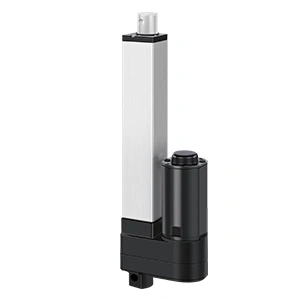
Why Self-Locking Force Matters in Vertical Lifting Applications
Learn how actuator self-locking force helps resist backdriving in vertical lifting systems—and what OEM engineers must check beyond dynamic load capacity.
When an electric linear actuator or electric lifting column is moving, the motor and transmission generate the force needed to raise or lower the load. But what happens when the motion stops?
More importantly, what happens when power is removed?
In a horizontal application, a small amount of backdriving may cause unwanted position drift. In a vertical lifting application, gravity continuously acts on the mechanism. If the actuator cannot resist that force, the platform, screen, work surface, cover, medical component, or machine assembly may slowly descend—or move much faster than expected.
This is why self-locking force, also described in some specifications as static holding force or static damping force, deserves its own place in the selection process.
It answers a question that dynamic load capacity does not fully answer:
How much axial load can the selected actuator configuration resist while stationary and unpowered without being driven backward by the load?
For OEM engineers and procurement teams, the important lesson is simple: an actuator that can lift a load under power is not automatically proven to hold that same load safely in every stopped, unpowered, or abnormal condition.
Table of Contents
What Is Self-Locking Force?
Self-locking force is the axial load that an unpowered actuator can resist without the external load causing the screw or transmission to backdrive.
Backdriving occurs when the load drives the mechanism in reverse. In a vertical system, gravity may push or pull the actuator rod, rotate the screw through the nut, and move the load downward even though the motor is no longer powered.
The simplified mechanics behind screw self-locking
For a screw mechanism, the first theoretical check compares the screw lead angle, α, with the friction angle, ρ. The lead angle at the screw’s mean diameter can be approximated as:
tan α = lead / (π × mean screw diameter)
For an ideal square thread, the simplified self-locking condition is:
α < ρ or tan α < μs
where μs is the static coefficient of friction between the screw and nut at the onset of motion. If the lead angle rises above the friction angle, an axial load can generate enough reverse torque to turn the screw, so the mechanism becomes backdrivable in the idealized model. This helps explain why a larger screw lead can increase travel per revolution—and speed—but reduce the natural resistance to backdriving.
Real trapezoidal threads require a more complete calculation. Their flank angle increases the effective friction term, so engineers normally compare the lead angle with an effective friction angle, ρ′, rather than using the square-thread equation without correction. A common simplified treatment for a symmetric trapezoidal thread with half-angle β uses μ′ ≈ μs / cos β and ρ′ = arctan μ′. Gearbox efficiency, bearing friction, screw and nut materials, lubrication, manufacturing tolerances, wear, temperature, vibration, and external torque also affect the finished actuator.
The equation is therefore a design-screening tool, not proof of a rated holding force. The final value must come from configuration-specific testing under defined conditions.
An actuator may resist backdriving through:
The geometry and friction of a lead-screw and nut system
The reduction ratio and friction inside the gearbox
An integrated holding or anti-backdrive brake
A separate mechanical locking or load-arresting device in the equipment
T-type or trapezoidal lead screws are often selected where compact linear motion and resistance to backdriving are useful. However, the words “T-type screw” or “self-locking” should not be treated as a complete system specification. Holding performance still depends on the exact screw lead, gear ratio, speed configuration, wear state, lubrication, load direction, temperature, vibration, and product design.
Lubrication deserves particular attention because it changes friction at the screw–nut interface. Grease viscosity also changes with temperature, while contamination, lubricant loss, oxidation, or an unsuitable relubrication interval can change friction and wear over time. A design that holds during a room-temperature bench test should therefore be validated across the specified temperature range and after representative service conditioning. Do not assume that cold, heat, or lubricant aging will always increase friction in a safe direction.
The correct value must come from the data for the selected model and configuration—not from a general assumption about the screw family.
Dynamic Load Is Not the Same as Holding Force
Dynamic load capacity describes how much force the actuator can push or pull while it is operating under defined conditions.
Self-locking force describes how much force the mechanism can resist while stationary, normally with power removed.
These ratings can be equal in some configurations. In others, they are different. A product table may show that an actuator can move a particular pull load but has a lower pull self-locking value at the same speed option. That difference matters when gravity acts in the pull direction after the motor stops.
The two questions should therefore be separated:
Engineering Question
Relevant Specification
Can the actuator raise or lower the load at the required speed?
Dynamic push/pull load under operating conditions
Can the stopped actuator resist the load when unpowered?
Static self-locking or holding force
Can the structure withstand a stationary load without permanent damage?
Permitted static structural load
Can people safely work beneath or near the raised load?
Complete risk assessment and independent safety measures where required
This distinction is especially important during power loss, emergency stop, controller fault, cable disconnection, maintenance, shipping, or long stationary periods.
Why Vertical Lifting Changes the Risk
In vertical motion, gravity does not switch off when the motor does.
The actuator must resist a persistent external force created by the supported mass and the mechanism geometry. A simplified starting point is:
Gravity load (N) = supported mass (kg) × 9.81 m/s²
But converting mass into force is only the beginning. The actuator may experience a higher force than the simple weight calculation suggests because of:
Lever arms or pivot geometry
An off-center center of gravity
Multiple supported components
Acceleration and deceleration
Impact or shock loading
Vibration during transport or equipment operation
Binding, poor alignment, or side load
Uneven load sharing in multi-column systems
User interaction or external forces
For this reason, the equipment designer should calculate the load at the actuator across the full stroke and operating geometry. The worst case may occur at one particular position rather than at the top or bottom of travel.
A safety margin should then be established from the equipment risk assessment, applicable standards, expected wear, manufacturing tolerances, environmental conditions, and supplier guidance. A universal margin should not be copied from an unrelated application.
Why Push and Pull Direction Matter
Many buyers request one number: “What is the actuator’s self-locking force?”
The more useful question is:
What is the self-locking force in the actual load direction for this exact motor, gear, screw, voltage, and speed configuration?
An actuator can have different push and pull holding values. The difference may become more pronounced in faster configurations. ActuLift catalog data, for example, includes configurations where dynamic push and pull capacities match but the pull self-locking value is lower than the push value.
The installation decides which figure matters. If gravity compresses the actuator, the push self-locking value may govern. If gravity pulls on the extension tube, the pull value may govern. A drawing of the mechanism and load direction is therefore more useful than a product name alone.
This is one reason an actuator should not be selected from maximum force in a page headline. The exact configuration code and mounting orientation must be reviewed.
The Speed–Load–Holding Trade-Off
Actuator speed is usually tied to gear ratio and screw lead. When evaluating a high-speed linear actuator, remember that changing the transmission to move faster can also change the available dynamic force and the resistance to backdriving.
ActuLift’s local product references illustrate two useful selection lessons:
Configurations with the same no-load speed can have different self-locking forces.
Higher-speed options can provide lower load and holding values than lower-speed options in the same product family.
That means “20 mm/s” is not a complete configuration. Two options with the same advertised speed may use different internal combinations and deliver different holding behavior.
The IP7180 catalog table provides a concrete example. Its listed speed options correspond to different load and self-locking values:
No-Load Speed
Dynamic Push/Pull Load
Push Self-Locking
Pull Self-Locking
4 mm/s
4,000 N
4,000 N
4,000 N
7 mm/s
3,000 N
3,000 N
3,000 N
20 mm/s
500 N
500 N
200 N
This is a configuration example, not a universal performance curve. Moving from the 4 mm/s option to the 20 mm/s option increases the listed no-load speed by five times, while the listed pull self-locking force falls from 4,000 N to 200 N. It also shows why dynamic pull capacity and pull holding force cannot be assumed to match: the 20 mm/s option lists a 500 N dynamic pull load but only 200 N of pull self-locking force.
The correct engineering response is not to conclude that “slow is always better.” It is to select a verified combination of speed, dynamic load, holding force, duty cycle, and—where necessary—an integrated brake or independent mechanical restraint.
For vertical lifting, select the holding requirement before treating maximum speed as the priority. A faster sample that drifts under load after power loss is not a better system.
Where Self-Locking Force Matters Most
TV and Monitor Lifts
A concealed TV or monitor lift may stop at different heights for long periods. The mechanism should maintain its intended position without visible drift, and the design must consider the effect of an elevated center of gravity.
Adjustable Workstations and Industrial Platforms
An elevated work surface may carry equipment, fixtures, or materials after movement has stopped. In industrial and mobile column lifts, load distribution, column synchronization, frame stiffness, and stationary holding performance should be reviewed as one system.
Medical and Rehabilitation Equipment
Medical positioning systems can involve people, caregivers, and frequent adjustments. Component self-locking data is useful for selection, but it does not replace the safety architecture, risk management, verification, and compliance work required for the final device.
Hatches, Covers, and Access Panels
The force at the actuator changes as a hinged cover moves through its arc. Gas springs, wind, center-of-gravity changes, and user forces may affect the worst-case holding requirement.
Industrial Machinery and Material Handling
Heavy-duty linear actuators may be used to move raised tooling, guards, fixtures, or assemblies, but these loads can create serious hazards if they descend unexpectedly. Where a falling load can injure a person or damage equipment, self-locking alone should not be treated as the only protective measure.
Self-Locking Is Not the Same as a Safety Lock
This distinction should be explicit in every vertical-axis project.
Self-locking is a performance characteristic of the actuator or transmission. A safety lock is part of a risk-reduction strategy designed around the complete machine and its foreseeable failure modes.
Depending on the risk, the equipment may require one or more additional measures:
A positive mechanical lock or support pin
A redundant brake or load-arresting device
Counterbalance or counterweight
A safety nut or secondary load path
Controlled lowering during power failure
Position and motion monitoring
Guards, exclusion zones, or maintenance supports
A safe bottom position for service access
A true load-catching safety nut is typically installed with a defined clearance behind or beside the primary load-bearing nut. It travels with the main assembly but does not carry the normal operating load. As the main nut wears, the clearance changes and can be inspected or monitored. If the main nut fractures or its threads can no longer support the load, the correctly oriented safety nut can take the axial load and limit a catastrophic drop. Its load direction, installation position, rated capacity, inspection limit, and post-engagement procedure must all be defined by the safety-nut manufacturer and the machine designer.
The terminology is not universal. Some products called “safety nuts” are primarily wear-indicator or follower nuts and may not be rated to catch the full load. Procurement specifications should therefore ask whether the device is only a wear monitor, a load-catching secondary nut, or both.
⚠️ Engineering safety warning Self-locking force, a motor holding brake, and an emergency-stop function are not automatically personnel fall-protection devices. If a person can enter beneath or beside a raised load, the machine-level risk assessment must define independent restraint, monitoring, maintenance supports, and validation requirements.
An emergency-stop function is intended to stop hazardous motion; it does not automatically prove that a vertical load will remain safely suspended afterward. Likewise, a motor brake or a self-locking screw may help hold position but should not be assumed to provide personnel protection without a system-level assessment.
If a person can enter beneath the load, the project requires particular caution. The machine designer must define the applicable safety requirements and validate the complete mechanism—not only the actuator datasheet.
For lifting tables within its defined scope, EN 1570-1:2024 is one example of a current product-safety standard that addresses significant hazards and technical risk-reduction measures. It should not be applied automatically to every actuator or lifting-column project: the relevant standard depends on the equipment type, travel, users, installation, market, and jurisdiction. Confirm applicability with the responsible machine-safety or compliance professional before turning a component feature into a compliance claim.
Common Specification Mistakes
Mistake 1: Using the lifting force as the holding force
Dynamic capacity and unpowered holding capacity are different specifications. Ask for both.
Mistake 2: Checking only the maximum family rating
The maximum number may belong to a slow, high-ratio configuration. Confirm the value for the actual speed and ordering code.
Mistake 3: Ignoring push versus pull
The installation orientation determines which value governs. Provide a mechanism drawing and indicate the direction of gravity loading.
Mistake 4: Treating a static rating as a personnel-safety guarantee
A component rating does not cover every failure mode in the final machine. Use independent protection where the risk assessment requires it.
Mistake 5: Ignoring side load and frame alignment
Self-locking values normally describe axial loading. Side loads, bending moments, poor bracket alignment, and frame distortion can cause wear or binding and should be handled by the mechanical structure, guides, and correctly selected brackets and mountings.
Mistake 6: Testing only when the product is new
Prototype validation should consider temperature, vibration, expected wear, load variation, repeated cycling, and the intended service interval—not only a new actuator on a clean bench.
Mistake 7: Treating lubrication and temperature as fixed conditions
Self-locking depends partly on friction, and friction is not a permanent material constant inside a working actuator. Verify the specified lubricant, relubrication or service interval, contamination controls, and holding behavior at the relevant cold and hot limits. Testing should also cover the aged or worn condition defined by the project risk assessment.
A Better Supplier Brief for Vertical Lifting Projects
Instead of asking:
“Do you have a self-locking lifting actuator?”
Send a brief that defines the system:
Application:
Equipment type: [name]
Part being lifted: [description]
People under or near raised load: [yes / no / possible]

Load:
Supported mass: [kg]
Calculated actuator force: [N]
Peak, shock, or external load: [N or description]
Load direction at actuator: [push / pull / changes through stroke]
Center of gravity and mechanism drawing: [attached]

Motion:
Stroke: [mm]
Required speed under load: [mm/s]
Target movement time: [seconds]
Operating angle: [vertical / angled / pivoting]

Holding:
Required unpowered holding force: [N]
Maximum hold duration: [time]
Permitted position drift: [mm over time]
Power-loss behavior required: [hold / controlled lower / safe position]

Operation:
Cycles per hour/day: [number]
Duty cycle: [run/rest pattern]
Ambient temperature: [range]
Vibration or shock: [description]

Integration:
Voltage: [12V / 24V / other]
Feedback or synchronization: [required / not required]
Controller: [type]
Independent brake or mechanical lock: [planned / required / unknown]
Mounting and guides: [drawing attached]
With this information, the supplier can compare the correct dynamic load, push/pull self-locking force, speed code, stroke, duty cycle, mounting arrangement, and compatible control boxes and controllers.
How to Validate the Selected System
Before production approval, test the complete equipment rather than the actuator alone.
Verify the exact configuration Match the model, voltage, speed or ratio code, stroke, screw option, controller, and mounting arrangement to the approved drawing and specification.
Test the worst-case load direction Include the position in the stroke where leverage, imbalance, or center-of-gravity effects create the highest actuator force.
Simulate loss of power Observe whether the load holds, creeps, coasts, or descends. Define an acceptable measurement period and drift limit before testing.
Repeat under realistic conditions Test at relevant temperatures and after representative cycling, vibration, transport, or wear conditioning where the application requires it.
Test fault and service scenarios Consider cable disconnection, controller failure, emergency stop, uneven multi-column movement, overload, and maintenance access.
Validate independent protection Where falling-load risk is significant, confirm that the mechanical lock, brake, support, or other protective measure works independently as intended.
Questions to Ask Before Approving an Actuator
Is the quoted force dynamic load, static structural load, or unpowered holding force?
Is the self-locking value specified for both push and pull directions?
Does the value apply to the exact speed and ratio code being ordered?
How much position drift is allowed, and over what test duration?
Under what temperature, mounting, wear, and vibration conditions was it tested?
Can the actuator backdrive if the external load exceeds the rating?
Is self-locking created by screw geometry, a brake, or both?
What happens during power loss or controller failure?
Are side loads or bending moments prohibited?
Does the application require a separate positive mechanical restraint?
Final Takeaway
Self-locking force is not a minor line in an actuator datasheet. In a vertical lifting system, it connects power-loss behavior, position stability, transmission design, load direction, speed selection, and equipment risk.
The strongest selection process separates three questions:
Can the actuator move the required load?
Can it hold the load when stopped and unpowered?
What independent protection is required if holding fails?
Answering only the first question can produce a prototype that moves correctly but does not behave safely or predictably when motion stops.
ActuLift supports OEM and equipment-manufacturing projects with linear actuators, lifting columns, controllers, and configuration review. For a vertical lifting application, share the load direction, mechanism drawing, stroke, speed, duty cycle, required holding force, control method, and power-loss behavior. Those details make it possible to recommend a motion system around the real application—not one maximum number on a product page.
FAQ
Is self-locking force the same as actuator load capacity?
Not necessarily. Load capacity normally describes powered motion, while self-locking or holding force describes resistance to backdriving when stationary and unpowered. Always check both values for the exact configuration.
Can a self-locking actuator hold a vertical load during power failure?
It may hold a load up to its specified rating under the stated conditions, but the equipment designer must validate the complete mechanism. If falling could injure people or damage equipment, use the risk assessment to determine whether an independent mechanical lock, brake, support, or other protective measure is required.
Why can two actuators with the same speed have different self-locking force?
The same output speed can be produced by different combinations of motor, gearing, and screw geometry. These internal differences can change both dynamic force and resistance to backdriving.
Does a T-type lead screw always prevent backdriving?
No universal assumption is safe. A trapezoidal lead screw can provide useful resistance to backdriving, but actual self-locking depends on the screw lead, friction, gear ratio, lubrication, wear, load, vibration, and overall actuator design. Use the specified and tested holding value for the selected model.
Should the holding force be higher than the expected vertical load?
The selected configuration should have adequate margin above the calculated worst-case actuator load. The required margin depends on the application risk, load uncertainty, geometry, shock, vibration, wear, environment, applicable standards, and supplier guidance; it should be defined by the equipment designer rather than copied as a universal percentage.
Get Expert Insights on Industrial Motion Control
Selecting the right electric linear actuator or lifting column is critical for your project's performance. As a professional Motion Control & Automation Manufacturer, our engineers help you customize load capacity, stroke length, and IP ratings based on your specific application. Share your technical requirements for a tailored solution.
ActuLift supports end-to-end customization, from structural design and stroke parameters to branding and casing finishes, helping you build a powerful brand identity.
Rapid Response & Prototyping
We understand the importance of speed in B2B procurement, utilizing optimized production workflows to ensure efficient responses from sample development to bulk delivery.
Stable Quality & Traceability
With ISO9001 quality assurance, every product—from material entry to final factory testing—is recorded in our electronic logs, ensuring high consistency in delivered goods.