5-Wire Linear Actuator Wiring Guide: Wires, Cable & Feedback
Learn how to identify actuator wires in a 5-wire linear actuator cable, separate motor from feedback/control conductors, verify the exact pinout, connect safely, and troubleshoot common wiring issues.
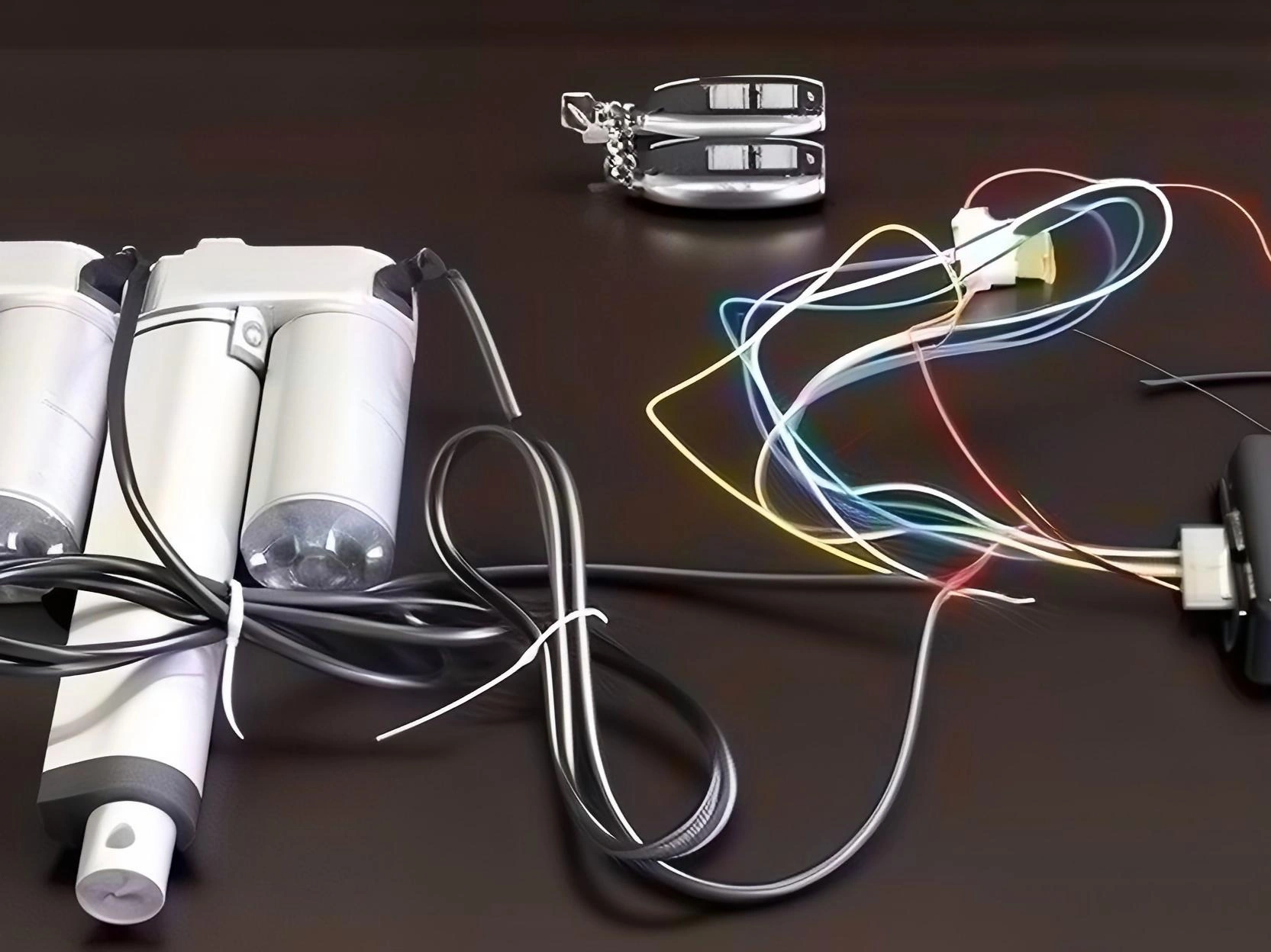
A 5-wire linear actuator is not one universal wiring standard. The actuator wires may combine motor power with limit-switch, potentiometer, Hall-effect, or other feedback/control conductors depending on the model. This linear actuator wiring guide starts with the exact actuator part number and wiring diagram, then identifies the motor and signal conductors before applying power.
Mục lục
Hiểu về Bộ truyền động thẳng 5 dây
A 5-wire cable usually means the actuator has more than the basic motor connection, but the extra conductors do not identify one specific feedback architecture. Depending on the actuator, they may carry end-limit signals, potentiometer position feedback, Hall-sensor power and pulses, low-level control inputs, or another model-specific interface.
Treat the actuator wiring diagram as the source of truth. Confirm the motor leads, feedback/control type, connector pinout, supply and signal levels, and any common/reference conductor for the exact configuration. Do not infer function from wire count or color alone.
Giải thích Mã màu dây
Wire colors are not standardized across actuator manufacturers or every option within one product family. Use colors only after matching them to the model-specific pinout.
Conductor group
Typical role
What to verify
Motor leads
Drive the actuator motor; many basic DC actuators reverse direction by polarity reversal
Rated voltage/current, lead identification, protection, and direction logic for the exact model
Feedback / signal conductors
May be limit switches, potentiometer, Hall-effect, voltage/current feedback, or low-level control
Feedback type, supply/reference, signal range, connector pins, and controller input compatibility
Common / reference
Signal return, excitation reference, or switch common when the selected interface uses one
Do not assume a universal color; use the model-specific wiring diagram
Connector / pin labels
Physical mapping between actuator and harness/controller
Lock the pinout and drawing revision for production and service documentation
Motor conductors and feedback/control conductors have different electrical requirements, but their colors, gauges, voltage levels, and current limits are configuration-specific. Size the motor circuit for the documented current and voltage drop, and connect signal conductors only to the interface specified for that actuator.
Danh sách kiểm tra an toàn trước khi đấu dây
Trước khi bắt đầu bất kỳ công việc đấu dây nào, hãy tuân theo những biện pháp an toàn cần thiết sau:
Ngắt điện — Luôn ngắt nguồn điện trước khi đấu dây. Rút phích cắm nguồn hoặc tháo kết nối pin.
Verify the exact configuration — Confirm rated supply voltage, motor current, feedback/control option, connector pinout, and signal levels for the selected part number.
Size the motor circuit correctly — Select conductor gauge, fuse/protection, connector, and cable length for the documented current, voltage drop, environment, and applicable wiring requirements.
Protect signal integrity — Where the actuator/controller documentation requires it, route low-level feedback/control conductors away from noisy motor wiring and use the specified grounding/shielding practice.
Hướng dẫn đấu dây từng bước
Bước 1: Xác định các dây của bạn
Identify the actuator part number and feedback option first. From the manufacturer wiring diagram, mark the motor leads and each signal/control conductor. If the documentation is missing or the cable has been modified, do not energize unknown signal wires; verify the circuit and pinout before connection.
Bước 2: Kết nối các dây nguồn
Connect the motor leads according to the actuator wiring diagram and the selected control method. Many basic DC actuators change direction by reversing polarity across the motor leads, while actuators with integrated electronics may use separate power and low-level direction inputs.
Motor lead A — Connect to the motor-control output specified by the actuator diagram; on many basic DC actuators, direction is controlled by polarity reversal.
Motor lead B — Connect to the complementary motor-control output. Do not assume red/blue or positive/negative mapping unless the selected model documents it.
Do not swap conductors as a troubleshooting shortcut unless the actuator documentation explicitly specifies polarity-reversal control. On feedback or electronically controlled models, applying power to the wrong conductor can damage the feedback circuit or controller input.
Bước 3: Kết nối các dây tín hiệu phản hồi
Connect the feedback/control conductors according to the documented interface. Typical possibilities include:
Limit-switch feedback — Use the documented common and end-limit contacts or outputs with compatible digital inputs; voltage and logic level depend on the model.
Potentiometer feedback — Connect excitation/reference and wiper to a compatible analog input exactly as specified for the potentiometer option.
Hall or electronic feedback/control — Provide the specified sensor/control supply and connect pulse, direction, or position outputs to compatible inputs per the model pinout.
The controller input type must match the actuator output. A dry-contact limit switch, analog potentiometer, Hall pulse, voltage/current output, and low-level direction input are electrically different interfaces and should not be wired interchangeably.
Bước 4: Kiểm tra đấu dây của bạn
Before final installation, test the wiring against the model documentation and the finished control system:
Verify supply voltage, current limit/fusing, motor lead mapping, and controller configuration before energizing the actuator.
Command a short, controlled movement and confirm that direction matches the documented control logic before running to an end position.
Verify each feedback signal with the appropriate input type: contact state, analog value, pulse train, or documented electronic output.
Confirm end-stop behavior, feedback range, controller interlocks, and fault response before the actuator is placed under the final mechanical load.
Cấu hình đấu dây phổ biến
Kiểm soát nút bấm trực tiếp
For a basic actuator that is explicitly designed for polarity-reversal motor control, a correctly rated center-off reversing switch, relay circuit, or H-bridge can provide manual extend/retract control. Keep any feedback conductors on their specified low-current interface.
Use a switch/relay/control device with the voltage and current rating required by the motor circuit.
Reverse motor polarity only when the actuator is explicitly designed for polarity-reversal direction control.
Keep feedback indicators or controller inputs on the documented feedback circuit; do not route motor current through signal conductors.
Tích hợp bộ điều khiển/PLC
For PLC or controller integration, map each documented actuator signal to a compatible input or output type and keep motor-current switching separate from low-level logic where the architecture requires it.
Map each feedback channel according to its documented function and electrical type rather than assuming an upper/lower-limit pair.
Configure digital, analog, pulse, voltage, or current inputs to match the selected feedback option and its specified range.
Implement end-stop, interlock, timeout, and fault behavior based on the actuator/controller documentation and finished-system risk analysis.
Khắc phục sự cố các vấn đề phổ biến
Bộ truyền động không di chuyển
Check the motor circuit — Verify the documented motor leads, supply voltage under load, fuse/protection, switching device, and connector continuity.
Kiểm tra điện áp tại cơ cấu chấp hành — Sử dụng đồng hồ vạn năng để xác nhận điện áp đúng đang đến cơ cấu chấp hành
Kiểm tra hư hỏng — Kiểm tra cáp xem có bị cắt hoặc bị nghiền nát không
Không có tín hiệu phản hồi giới hạn
Verify the feedback reference — Confirm the exact common, ground, excitation, or reference conductor required by the selected feedback option.
Test the correct signal type — Use continuity, resistance, voltage, current, or pulse measurement only as appropriate for the documented feedback architecture.
Check controller compatibility — Confirm input type, voltage range, pull-up/pull-down requirements, grounding, and logic interpretation.
Hoạt động không liên tục
Kiểm tra kết nối dây — Kết nối lỏng có thể gây ra hoạt động không ổn định
Measure voltage drop under load — If supply voltage at the actuator falls outside the allowed range, correct conductor sizing, connections, power supply, or cable length.
Tách biệt dây tín hiệu và dây nguồn — Giữ dây tín hiệu xa khỏi dây động cơ để giảm nhiễu
Sự khác biệt giữa bộ truyền động thẳng 2 dây và 5 dây là gì?
A 2-wire actuator commonly exposes only the motor circuit and changes direction by polarity reversal. A 5-wire cable indicates additional conductors, but their function is not universal: depending on the model they may be limit-switch, potentiometer, Hall-effect, low-level control, or another feedback interface. Verify the exact wiring diagram.
Tôi có thể đi dòng điện qua các dây phản hồi mỏng không?
Do not apply motor power to any conductor identified as feedback or control. Wire gauge and color are not universal, so identify the exact motor and signal pins from the selected model documentation before energizing the cable.
Làm thế nào tôi biết dây nào là đất chung cho phản hồi?
There is no universal common-ground color for all 5-wire actuators. Some feedback types use a common, some use excitation and a wiper, and others use sensor supply/ground plus pulse outputs. Use the exact model pinout and electrical specification.
Tôi có cần một bộ điều khiển để sử dụng bộ truyền động 5 dây không?
It depends on the actuator architecture. A basic motor may only need a suitable reversing switch or relay circuit, while feedback signals require compatible controller inputs. Models with integrated electronics may require dedicated power and low-level direction/control connections.
Chọn bộ truyền động tuyến tính phù hợp
Nếu bạn đang chọn một bộ kích hoạt tuyến tính cho dự án của mình, hãy xem xét những tùy chọn sau:
Bộ truyền động tuyến tính 12V — Evaluate for systems using 12V power after confirming load, current, wiring, controller, environmental, and application requirements
Bộ truyền động tuyến tính 24V — Evaluate where 24V power and the selected actuator/controller architecture fit the equipment requirements
For OEM programs: lock the feedback type, connector/pinout, cable length, supply voltage and current, controller interface, environmental requirements, and wiring-document revision before production. See Custom OEM/ODM Solutions for the project workflow.
ActuLift hỗ trợ tùy chỉnh từ đầu đến cuối, từ thiết kế cấu trúc và tham số hành trình đến thương hiệu và hoàn thiện vỏ, giúp bạn xây dựng bản sắc thương hiệu mạnh mẽ.
Phản hồi nhanh & Tạo mẫu
Chúng tôi hiểu tầm quan trọng của tốc độ trong việc mua sắm B2B, sử dụng quy trình sản xuất được tối ưu hóa để đảm bảo phản hồi hiệu quả từ phát triển mẫu đến giao hàng số lượng lớn.
Quality Documentation & Traceability
Quality and traceability requirements vary by project. Ask ActuLift for the applicable inspection records, product specifications, drawings and available compliance documentation for the selected model and order.