5-Wire Linear Actuator Wiring Guide: Wires, Cable & Feedback
Learn how to identify actuator wires in a 5-wire linear actuator cable, separate motor from feedback/control conductors, verify the exact pinout, connect safely, and troubleshoot common wiring issues.
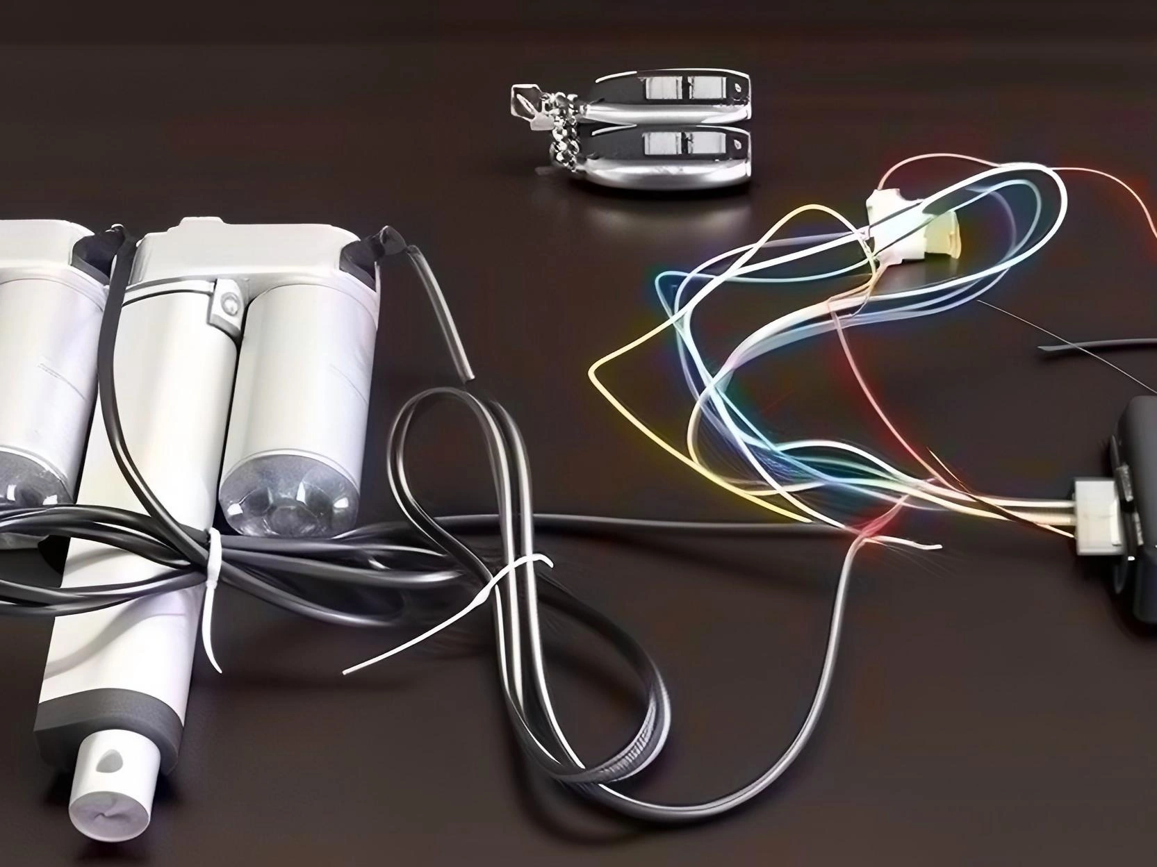
A 5-wire linear actuator is not one universal wiring standard. The actuator wires may combine motor power with limit-switch, potentiometer, Hall-effect, or other feedback/control conductors depending on the model. This linear actuator wiring guide starts with the exact actuator part number and wiring diagram, then identifies the motor and signal conductors before applying power.
สารบัญ
เข้าใจตัวกระตุ้นเชิงเส้น 5 สาย
A 5-wire cable usually means the actuator has more than the basic motor connection, but the extra conductors do not identify one specific feedback architecture. Depending on the actuator, they may carry end-limit signals, potentiometer position feedback, Hall-sensor power and pulses, low-level control inputs, or another model-specific interface.
Treat the actuator wiring diagram as the source of truth. Confirm the motor leads, feedback/control type, connector pinout, supply and signal levels, and any common/reference conductor for the exact configuration. Do not infer function from wire count or color alone.
อธิบายรหัสสีของสาย
Wire colors are not standardized across actuator manufacturers or every option within one product family. Use colors only after matching them to the model-specific pinout.
Conductor group
Typical role
What to verify
Motor leads
Drive the actuator motor; many basic DC actuators reverse direction by polarity reversal
Rated voltage/current, lead identification, protection, and direction logic for the exact model
Feedback / signal conductors
May be limit switches, potentiometer, Hall-effect, voltage/current feedback, or low-level control
Feedback type, supply/reference, signal range, connector pins, and controller input compatibility
Common / reference
Signal return, excitation reference, or switch common when the selected interface uses one
Do not assume a universal color; use the model-specific wiring diagram
Connector / pin labels
Physical mapping between actuator and harness/controller
Lock the pinout and drawing revision for production and service documentation
Motor conductors and feedback/control conductors have different electrical requirements, but their colors, gauges, voltage levels, and current limits are configuration-specific. Size the motor circuit for the documented current and voltage drop, and connect signal conductors only to the interface specified for that actuator.
Verify the exact configuration — Confirm rated supply voltage, motor current, feedback/control option, connector pinout, and signal levels for the selected part number.
Size the motor circuit correctly — Select conductor gauge, fuse/protection, connector, and cable length for the documented current, voltage drop, environment, and applicable wiring requirements.
Protect signal integrity — Where the actuator/controller documentation requires it, route low-level feedback/control conductors away from noisy motor wiring and use the specified grounding/shielding practice.
คำแนะนำการเดินสายทีละขั้นตอน
ขั้นตอนที่ 1: ระบุสายของคุณ
Identify the actuator part number and feedback option first. From the manufacturer wiring diagram, mark the motor leads and each signal/control conductor. If the documentation is missing or the cable has been modified, do not energize unknown signal wires; verify the circuit and pinout before connection.
ขั้นตอนที่ 2: เชื่อมต่อสายไฟ
Connect the motor leads according to the actuator wiring diagram and the selected control method. Many basic DC actuators change direction by reversing polarity across the motor leads, while actuators with integrated electronics may use separate power and low-level direction inputs.
Motor lead A — Connect to the motor-control output specified by the actuator diagram; on many basic DC actuators, direction is controlled by polarity reversal.
Motor lead B — Connect to the complementary motor-control output. Do not assume red/blue or positive/negative mapping unless the selected model documents it.
Do not swap conductors as a troubleshooting shortcut unless the actuator documentation explicitly specifies polarity-reversal control. On feedback or electronically controlled models, applying power to the wrong conductor can damage the feedback circuit or controller input.
ขั้นตอนที่ 3: เชื่อมต่อสายส่งสัญญาณย้อนกลับ
Connect the feedback/control conductors according to the documented interface. Typical possibilities include:
Limit-switch feedback — Use the documented common and end-limit contacts or outputs with compatible digital inputs; voltage and logic level depend on the model.
Potentiometer feedback — Connect excitation/reference and wiper to a compatible analog input exactly as specified for the potentiometer option.
Hall or electronic feedback/control — Provide the specified sensor/control supply and connect pulse, direction, or position outputs to compatible inputs per the model pinout.
The controller input type must match the actuator output. A dry-contact limit switch, analog potentiometer, Hall pulse, voltage/current output, and low-level direction input are electrically different interfaces and should not be wired interchangeably.
ขั้นตอนที่ 4: ทดสอบการเดินสายของคุณ
Before final installation, test the wiring against the model documentation and the finished control system:
Verify supply voltage, current limit/fusing, motor lead mapping, and controller configuration before energizing the actuator.
Command a short, controlled movement and confirm that direction matches the documented control logic before running to an end position.
Verify each feedback signal with the appropriate input type: contact state, analog value, pulse train, or documented electronic output.
Confirm end-stop behavior, feedback range, controller interlocks, and fault response before the actuator is placed under the final mechanical load.
การกำหนดค่าเดินสายทั่วไป
การควบคุมด้วยปุ่มกดโดยตรง
For a basic actuator that is explicitly designed for polarity-reversal motor control, a correctly rated center-off reversing switch, relay circuit, or H-bridge can provide manual extend/retract control. Keep any feedback conductors on their specified low-current interface.
Use a switch/relay/control device with the voltage and current rating required by the motor circuit.
Reverse motor polarity only when the actuator is explicitly designed for polarity-reversal direction control.
Keep feedback indicators or controller inputs on the documented feedback circuit; do not route motor current through signal conductors.
การบูรณาการคอนโทรลเลอร์/PLC
For PLC or controller integration, map each documented actuator signal to a compatible input or output type and keep motor-current switching separate from low-level logic where the architecture requires it.
Map each feedback channel according to its documented function and electrical type rather than assuming an upper/lower-limit pair.
Configure digital, analog, pulse, voltage, or current inputs to match the selected feedback option and its specified range.
Implement end-stop, interlock, timeout, and fault behavior based on the actuator/controller documentation and finished-system risk analysis.
การแก้ปัญหาส่วนที่พบบ่อย
ตัวกระตุ้นไม่เคลื่อนที่
Check the motor circuit — Verify the documented motor leads, supply voltage under load, fuse/protection, switching device, and connector continuity.
Verify the feedback reference — Confirm the exact common, ground, excitation, or reference conductor required by the selected feedback option.
Test the correct signal type — Use continuity, resistance, voltage, current, or pulse measurement only as appropriate for the documented feedback architecture.
Check controller compatibility — Confirm input type, voltage range, pull-up/pull-down requirements, grounding, and logic interpretation.
Measure voltage drop under load — If supply voltage at the actuator falls outside the allowed range, correct conductor sizing, connections, power supply, or cable length.
A 2-wire actuator commonly exposes only the motor circuit and changes direction by polarity reversal. A 5-wire cable indicates additional conductors, but their function is not universal: depending on the model they may be limit-switch, potentiometer, Hall-effect, low-level control, or another feedback interface. Verify the exact wiring diagram.
ฉันสามารถส่งไฟฟ้าผ่านสายฟีดแบคที่บางได้หรือไม่?
Do not apply motor power to any conductor identified as feedback or control. Wire gauge and color are not universal, so identify the exact motor and signal pins from the selected model documentation before energizing the cable.
There is no universal common-ground color for all 5-wire actuators. Some feedback types use a common, some use excitation and a wiper, and others use sensor supply/ground plus pulse outputs. Use the exact model pinout and electrical specification.
It depends on the actuator architecture. A basic motor may only need a suitable reversing switch or relay circuit, while feedback signals require compatible controller inputs. Models with integrated electronics may require dedicated power and low-level direction/control connections.
แอกทูเอเตอร์เชิงเส้น 12V — Evaluate for systems using 12V power after confirming load, current, wiring, controller, environmental, and application requirements
แอกทูเอเตอร์เชิงเส้น 24V — Evaluate where 24V power and the selected actuator/controller architecture fit the equipment requirements
For OEM programs: lock the feedback type, connector/pinout, cable length, supply voltage and current, controller interface, environmental requirements, and wiring-document revision before production. See Custom OEM/ODM Solutions for the project workflow.
Quality and traceability requirements vary by project. Ask ActuLift for the applicable inspection records, product specifications, drawings and available compliance documentation for the selected model and order.