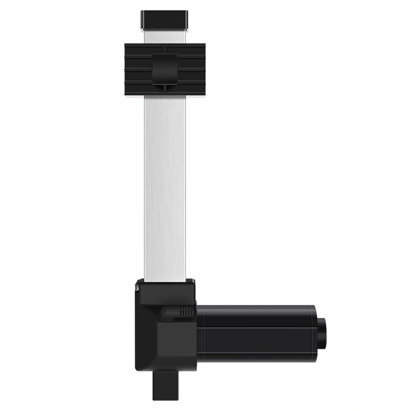
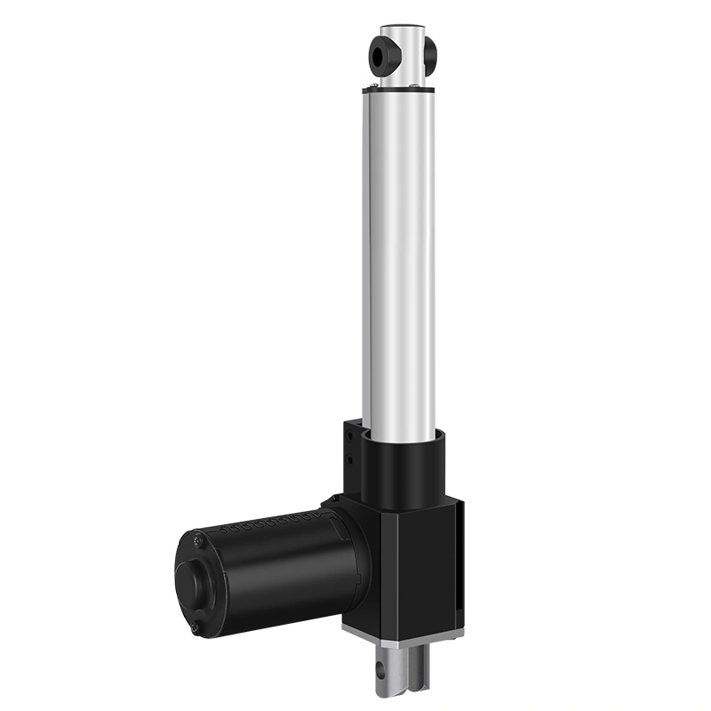
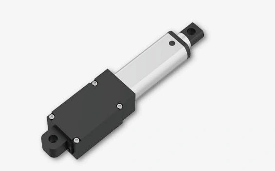
Verwirrt von den Zyklusbewertungen? Erfahren Sie genau, was "10% Arbeitszyklus" für Ihren linearen Aktuator bedeutet, wie Sie ON/OFF-Zeiten berechnen und professionelle Tipps erhalten, um eine Überhitzung des Motors zu verhindern und die Lebensdauer der Geräte zu verlängern.
Actuator duty cycle describes how long an actuator can run within a fixed time period before it needs to rest. For example, a 10% duty cycle often means the actuator can operate for 2 minutes and then rest for 18 minutes in a 20-minute cycle. Choosing the wrong duty cycle can cause overheating, unstable performance, or reduced service life.
Inhalt
Was ist der Duty Cycle bei linearen Aktuatoren?
Arbeitszyklus describes the permitted ON/OFF operating pattern under specified load, ambient and thermal conditions. The reference interval is product-specific; do not assume a universal 10-minute interval.
Motor operation generates heat, and allowable run/rest timing depends on the motor, gearing, load, speed, enclosure, ambient temperature and thermal design. Use the selected actuator’s documented duty-cycle condition rather than a generic analogy as an engineering limit.
Die Mathematik hinter dem Duty Cycle
Angenommen, Sie sehen „10% (2 Minuten EIN / 18 Minuten AUS)“ in einer Aktuatorspezifikation. Hier ist, was das bedeutet:
For a product explicitly rated “2 min ON / 18 min OFF,” that pattern should be treated as the documented operating limit under the stated test conditions. Exceeding it can increase thermal stress, but the exact temperature rise and failure mode depend on the selected motor and application.
Warum der Duty Cycle wichtig ist: Überhitzung des Motors verhindern
Duty-cycle limits are often driven partly by thermal behavior. Motor winding, gearing, lubrication, enclosure and ambient conditions can all affect the allowable operating pattern. When a system exceeds its documented limits, possible effects include:
1. Thermisches Durchgehen
Higher temperature changes winding resistance and can increase thermal stress. Whether this becomes a runaway condition depends on the motor/control design, load, supply and cooling; do not assume destruction within a fixed number of minutes.
2. Isolationsfehler
Motor insulation has temperature limits, and excessive thermal exposure can accelerate insulation degradation. Failure timing and mode depend on insulation class, temperature history and the complete motor design.
3. Lagerbeschädigung
Higher temperature can also affect bearings, gearing and lubricants. The effect depends on the selected components, lubrication and actual temperature/time profile.
4. Verkürzte Lebensdauer
Repeated operation above the documented thermal limits can reduce component life, but there is no universal “every 10°C halves life” rule that should be applied to every actuator without the relevant motor/material data.
Häufige Duty Cycle Bewertungen erklärt
Duty-cycle specifications can be expressed in different ways. The examples below illustrate arithmetic only; they are not universal application recommendations:
Example duty cycle
Illustrative ON time
Illustrative OFF time
How to use it
10%
2 min
18 min
Arithmetic example only; confirm the selected product’s stated interval and conditions
25%
2,5 min
7,5 min
Example over a 10-minute interval; product documentation may use another interval
50%
5 min
5 min
Example over a 10-minute interval; not a generic “continuous-use” rating
100%
Kontinuierlich
Keine
Only when the selected actuator/system is explicitly rated for continuous operation under the stated conditions
Do not choose a duty cycle from broad labels such as consumer, light industrial or continuous-use. Derive the required ON/OFF pattern from the actual motion profile, load, ambient conditions and selected actuator documentation.
Wie man den richtigen Duty Cycle für Ihre Anwendung wählt
Die Auswahl des richtigen Arbeitszyklus erfordert ein Verständnis Ihres spezifischen Anwendungsfalls. Fragen Sie sich:
Wie lange dauert jede Bewegung? Measure the actual travel time for the selected stroke, speed and load rather than assuming a typical desk run time or that 10% will suffice.
Wie häufig wird der Aktuator betrieben? Ein Aktuator, der einmal pro Tag anpasst, hat ganz andere Anforderungen als einer, der alle paar Minuten arbeitet.
What is the load? Load affects motor current and thermal behavior, but the relationship is configuration-specific. Use the selected actuator’s load/speed/current/duty data.
What are the thermal conditions? Ambient temperature, enclosure, airflow and nearby heat sources can affect thermal margin; confirm the actual installation conditions.
Anwendungsbeispiele
Sit-stand desks: define actual travel time, expected adjustment frequency, load and controller behavior, then verify the selected column/actuator duty rating.
Industrial doors or access mechanisms: derive duty requirements from cycle frequency, travel time, load, temperature and required service profile; do not use a generic 25–50% recommendation.
Care-related or regulated equipment: finished-device duty, thermal, safety and regulatory requirements must be defined for the actual mechanism; there is no universal 50–100% actuator duty requirement.
Agricultural machinery: duty varies by mechanism and task; define the real cycle and environment rather than assuming a 25% minimum.
ActuLift Product Evidence: Verify by Configuration
ActuLift actuator platforms are configuration-specific. For duty-cycle or thermal decisions, use the selected product’s approved load, speed, current, duty/thermal limits, ambient conditions and supporting documentation rather than a brand-wide durability assumption.
Thermal Design Evidence
Do not assume a particular winding grade, slot design or thermal-conductivity advantage across all ActuLift motors. If thermal performance matters, request the selected motor/actuator configuration’s current, duty-cycle, temperature and validation data.
Bearings & Gearing Evidence
Bearings, gearing, lubrication and continuous-duty capability are product/configuration dependent. Confirm the selected design, duty limits, acoustic requirements and maintenance expectations instead of inferring longer life or quieter operation.
Testing Evidence
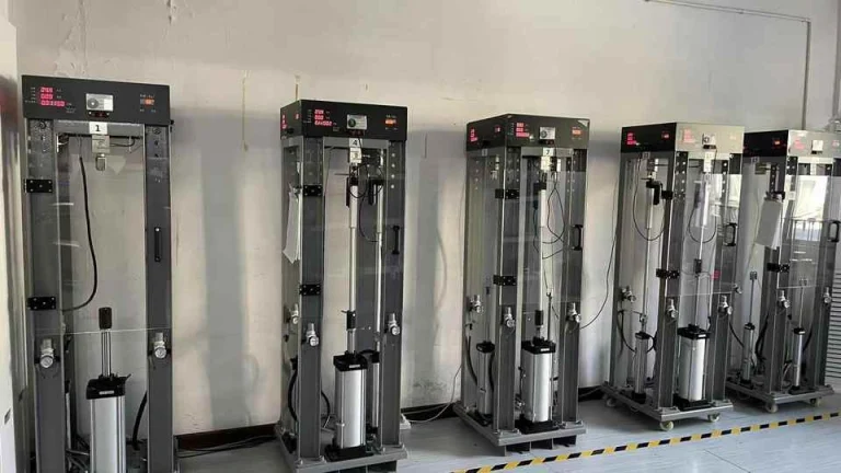
Do not assume every actuator has undergone the same thermal-cycling or beyond-rating test program. Request the test records, inspection scope or validation evidence applicable to the selected product and order when required.
Duty-Cycle Options
Use the Schwere Linearantriebe category to identify candidate products, then confirm the selected build’s actual duty-cycle/thermal rating, load, speed and environmental conditions. The category name does not establish continuous or near-continuous operation.
Operating Practices for Duty-Cycle Compliance
Use these practices to stay within the selected actuator’s documented operating envelope. They are not a guarantee of service life:
Enforce the documented interval in the control logic where supported. A compatible controller or PLC can help the system respect the selected actuator’s stated ON/OFF condition instead of relying only on operator memory.
Track actual motor-energized ON time against the manufacturer-defined reference interval when the control architecture can measure it.
When the allowed ON time is reached, inhibit further movement until the documented OFF/cooling interval has been satisfied.
Use temperature, current or fault inputs only when the selected actuator/controller explicitly supports them and their limits are documented.
Control logic does not increase the actuator’s duty-cycle rating. If the required motion profile exceeds the documented limit, select a configuration explicitly rated for that profile.
For controller candidates, review Steuerkästen und Controller, then verify compatibility, timing behavior, current limits and fault handling for the selected actuator and finished system.
1. Innerhalb der Nennspezifikationen bleiben
Operate within the documented duty-cycle, load, speed, ambient and controller limits. If the real motion profile exceeds them, select a configuration explicitly rated for that profile rather than relying on extra rest later.
2. Ausreichende Kühlzeit zulassen
Follow the product’s specified OFF/cooling interval and ambient-temperature limits. Do not invent a cooling time that differs from the documented duty-cycle condition.
3. Lastbedingungen überwachen
Load affects current, speed and thermal behavior, but there is no universal 50–70% sizing rule. Size the actuator from the actual static, dynamic, holding and safety-factor requirements plus the selected product’s approved load/duty data.
4. Sicherstellen, dass die Spannung korrekt ist
Use the documented supply-voltage range and size the power source, controller and wiring for rated/peak current and voltage drop. The effect of undervoltage depends on the motor/controller architecture and load.
5. Richtige Montage sicherstellen
Keep the actuator within its approved mounting/alignment, side-load and load-path limits. Mechanical binding or side load can change force, current, wear and thermal behavior.
Kann ich einen Aktuator mit 10% Duty Cycle 5 Minuten lang betreiben, wenn ich ihn 45 Minuten lang ausruhe?
Not if the selected product is explicitly specified as 2 min ON / 18 min OFF. Duty-cycle limits are defined by the manufacturer’s stated interval and conditions; extra rest afterward does not automatically make a longer uninterrupted run acceptable. Use the exact selected-product specification.
Beeinflusst das Lastgewicht den Duty Cycle?
It can. Load changes motor current, speed and thermal behavior, but the relationship is configuration-specific. Use the selected actuator’s load/current/speed/duty data and any required derating rather than assuming a generic higher-duty or higher-force solution.
Was passiert, wenn der Aktuator zu heiß wird?
Stop operation and follow the selected product’s thermal/fault guidance. Excess temperature can indicate an excessive duty cycle, load, ambient condition, supply/control issue or mechanical binding. Do not assume every ActuLift model includes thermal protection; confirm the exact configuration.
Die richtige Wahl treffen
Duty cycle is one selection input alongside load, speed, stroke, supply, controller, ambient conditions and mounting. Match the real motion profile to the selected actuator’s documented operating limits and validate the complete mechanism.
Use the Linearantriebe category to identify candidate product families, then confirm duty cycle, load, speed, stroke, controls and environment for the selected configuration.
For configuration review, provide the required ON/OFF profile, load, stroke, speed, supply, controller, mounting and environmental conditions so candidate products can be compared against current documentation.
Final actuator suitability depends on the selected configuration and finished-system validation.
IEEE Xplore:technical literature database; identify and review the actual paper before applying a thermal rule to a specific motor.
Erhalten Sie Experteneinblicke in die industrielle Bewegungssteuerung
Die Auswahl des richtigen elektrischen linearen Aktuators oder Hebensäule ist entscheidend für die Leistung Ihres Projekts. Als professioneller Hersteller von Bewegungssteuerungen & Automatisierung, helfen unsere Ingenieure Ihnen, die Lastkapazität, den Hub, und die IP-Bewertungen basierend auf Ihrer spezifischen Anwendung anzupassen. Teilen Sie uns Ihre technischen Anforderungen für eine maßgeschneiderte Lösung mit.
ActuLift unterstützt End-to-End-Anpassungen, vom strukturellen Design und Hubparametern bis hin zu Branding und Gehäusefinishes, damit Sie eine starke Markenidentität aufbauen können.
Schnelle Reaktion & Prototyping
Wir verstehen die Bedeutung von Geschwindigkeit in der B2B-Beschaffung und nutzen optimierte Produktionsabläufe, um effiziente Antworten von der Mustentwicklung bis zur Serienlieferung sicherzustellen.
Quality Documentation & Traceability
Quality and traceability requirements vary by project. Ask ActuLift for the applicable inspection records, product specifications, drawings and available compliance documentation for the selected model and order.