The Ultimate Guide to Electric Linear Actuators (2026 Edition)
Learn how to choose an electric linear actuator by load, stroke, speed, voltage, duty cycle, feedback, IP rating, and mounting space for OEM and industrial equipment projects.
Choosing the right electric linear actuator starts with six core parameters: load, stroke, speed, voltage, duty cycle, and installation space. For OEM equipment, you also need to consider feedback control, IP rating, noise level, cable routing, mounting brackets, and long-term reliability. This guide explains how to define those requirements before selecting or customizing an actuator.
Daftar Isi
1. Introduction: What Is an Electric Linear Actuator?
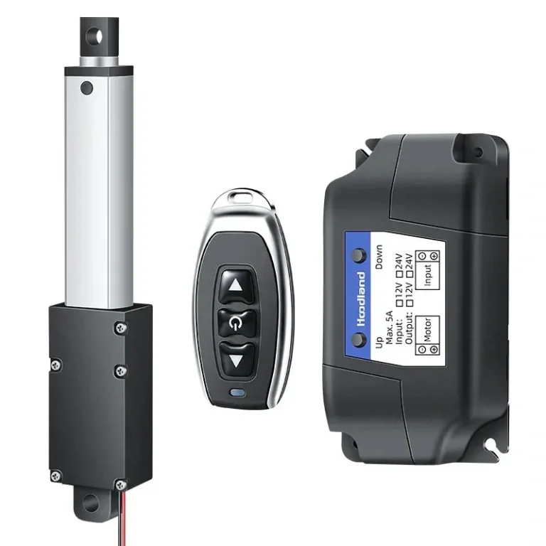
An electric linear actuator is a mechanical device that converts electrical energy into precise linear (straight-line) motion. Electric linear actuators can offer clean integration and controllable motion, but the appropriate technology depends on load, speed, duty cycle, environment, controls, safety requirements and the finished system.
Electric linear actuators are used across automation, furniture, transportation, renewable-energy and other OEM equipment. Selection should be based on the project requirements rather than a general market trend. Understanding how to select and apply these devices is essential for engineers, designers, and procurement professionals alike.
This comprehensive guide covers everything you need to know about electric linear actuators—from fundamental working principles to advanced selection criteria, installation best practices, and troubleshooting techniques.
2. Working Principle: How Electric Linear Actuators Convert Rotary Motion to Linear Motion
Electric linear actuators operate through a sophisticated conversion process that transforms the rotational output of an electric motor into controlled linear motion. Understanding this principle is fundamental to selecting the right actuator for your application.
The Core Conversion Mechanism
At its heart, an electric linear actuator consists of three primary components working in sequence:
Motor: The electric motor (typically DC brushless or brushed) generates rotational force (torque) when electrical current is applied.
Gear Train: A series of gears reduces motor speed while increasing torque. This gear reduction is crucial because linear actuators require high force at low speeds—far different from the high-speed, low-torque output of direct motor operation.
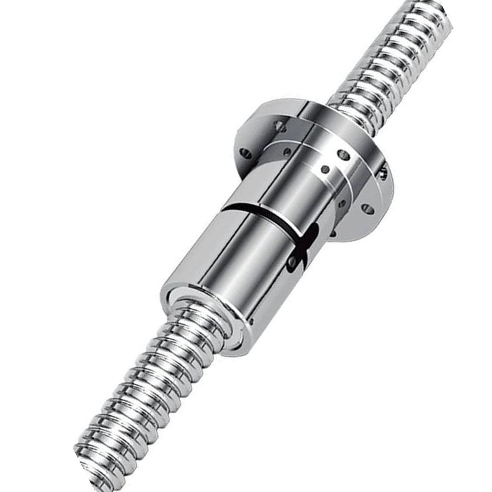
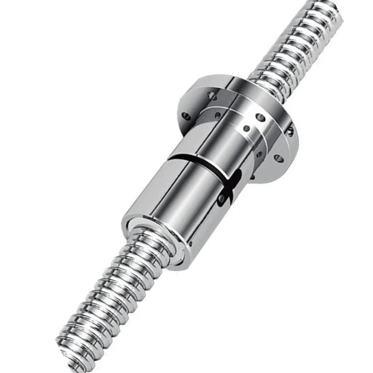
Lead Screw or Ball Screw: The heart of the conversion mechanism. The rotational motion from the gear train drives a threaded shaft (lead screw) or ball-bearing screw. As the screw rotates, a nut traveling along the threads converts this rotation into linear movement.
Key Mechanical Concepts
Sudut Pemandu: The angle of the screw thread determines how much linear travel occurs per rotation. A higher lead angle means faster linear movement but typically less lifting force.
Self-Locking vs. Non-Self-Locking: Some actuator designs can resist back-driving after power is removed. Holding behavior is configuration-dependent and must be verified for the selected screw, gearing, load, orientation, wear state and system safety architecture. For applications requiring backdriving, understanding the static self-locking force in linear actuators is essential.
Efficiency: Ball screws and sliding lead screws can have different efficiency characteristics, but the actual value depends on geometry, preload, lubrication, load, speed and the selected design. Use configuration-specific data when sizing power and thermal performance.
3. Types of Electric Linear Actuators
Choosing the right actuator type is critical for optimal performance. Each design offers distinct advantages for specific applications.
3.1 Inline Linear Actuators
Inline (or “直列式”) actuators feature the motor mounted in line with the screw shaft. This compact design is ideal for space-constrained applications where the actuator must fit within narrow envelopes.
Common evaluation contexts: Cabinetry and other space-constrained equipment; medical, automotive, or regulated uses require project- and finished-system validation
Karakteristik:
Jejak yang kompak
Lower cost compared to parallel designs
Limited motor size options
Force: confirm the rated moving and holding load for the selected inline actuator and test conditions
3.2 Parallel Linear Actuators
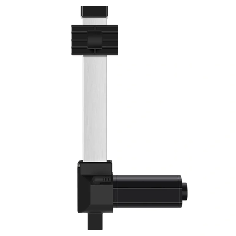
In parallel configurations, the motor mounts perpendicular to the screw, connected via a gearbox. This design allows for larger motors and higher force capabilities.
Common evaluation contexts: Industrial mechanisms, lifting-column systems, and vehicle-related equipment when the selected configuration meets the project load, control, mounting, safety, and validation requirements
Karakteristik:
Force capacity depends on the selected motor, gearbox, screw, housing, duty cycle and configuration
More flexible mounting options
Larger envelope size
Better heat dissipation
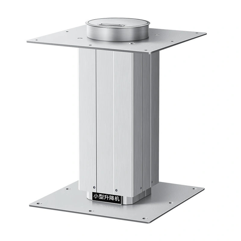
3.3 Lifting Columns
Lifting columns (升降柱) are multi-stage actuators designed specifically for vertical lifting applications. They feature nested tube sections that extend telescopically. For system-level effects of extension, side load, frame stiffness and multi-column control, see our lifting column stability guide.
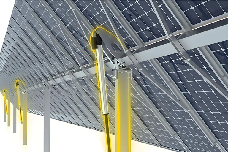
Common evaluation contexts: Adjustable-height desks and other vertical-motion systems; patient-lift, industrial, and solar-tracking use must be evaluated at the finished-system level
Karakteristik:
Multiple stages (typically 2-4)
Smooth, stable lifting motion
High load capacity
Esthetic appearance for consumer products
3.4 Telescopic Linear Actuators
Telescopic actuators offer the longest stroke lengths through nested barrel sections. They’re designed for applications requiring significant linear travel in compact retracted lengths.
Common evaluation contexts: Long-travel equipment where the selected actuator’s load, stroke, retracted/extended length, alignment, duty cycle, and environment are validated
Karakteristik:
Extended travel is configuration-dependent; confirm stroke, retracted/extended length, critical speed and alignment requirements
Voltage selection is one of the most critical decisions in actuator selection. The choice impacts everything from power supply requirements to performance characteristics.
12V DC Linear Actuators
Often evaluated for automotive and mobile architectures that use 12V power, subject to load, current, wiring, controller, duty-cycle, environmental, and finished-system requirements
Operates directly from vehicle batteries
Speed and force are configuration-dependent; do not infer performance from voltage alone
For marine-related equipment, confirm corrosion, sealing, wiring, duty-cycle, and finished-system requirements rather than selecting by voltage alone
Common in some industrial control architectures; confirm the actual site supply and controller
Force and speed depend on the selected motor, gearing, screw and working load rather than voltage alone
Efficiency, thermal performance and duty cycle are configuration-dependent
Confirm compatibility with the factory power and control architecture
Selection item
What to confirm
Supply voltage
Available power architecture, controller compatibility and wiring losses
Load / speed
Configuration-specific performance at the expected working point
Current draw
Startup, running and stall-current requirements for the selected build
Lingkungan
Connector, cable, enclosure and protection requirements
Integrasi sistem
Battery, vehicle or industrial supply constraints and applicable controls
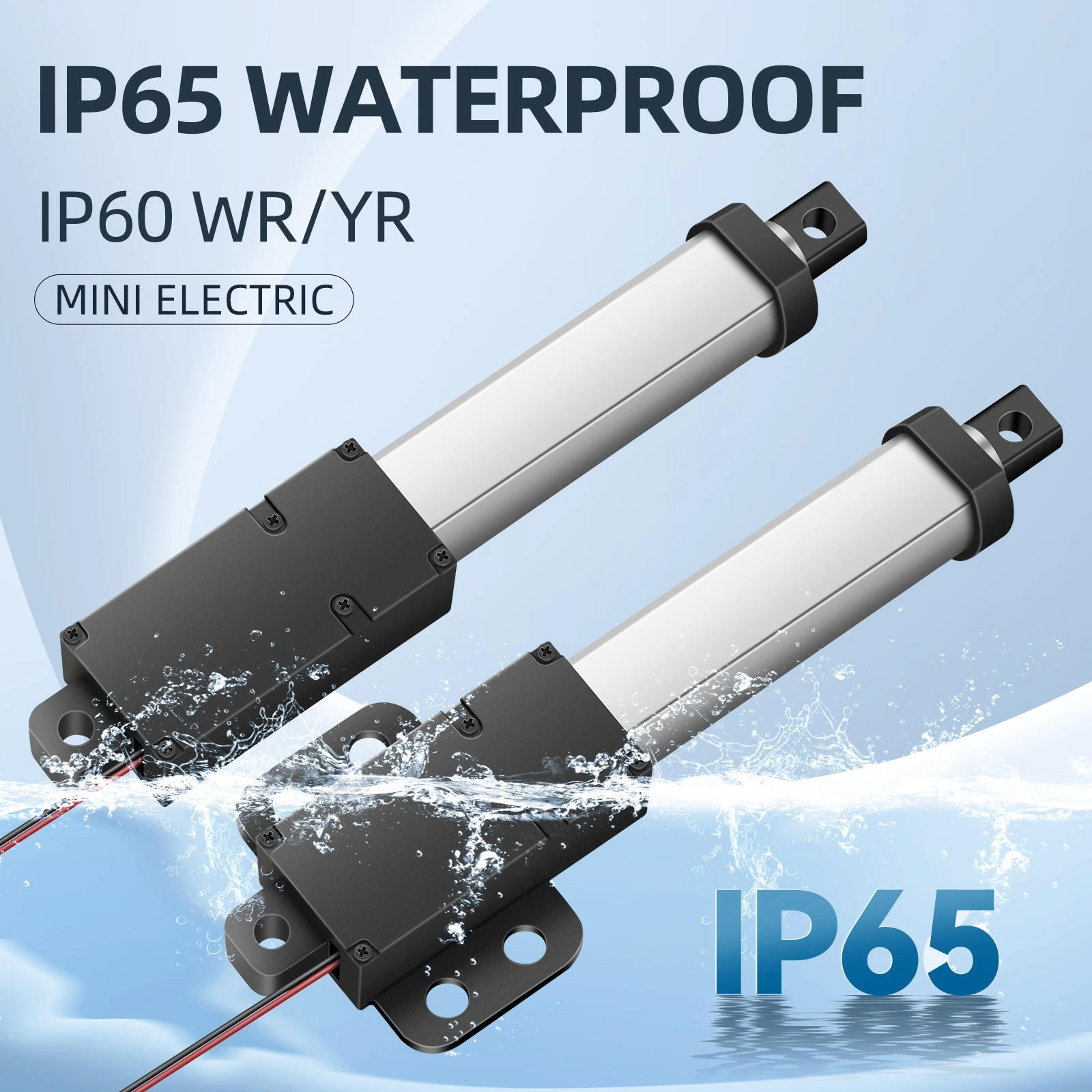
4.2 IP Protection Ratings
IP (Ingress Protection) ratings define how well an actuator is protected against solid objects and liquids. This specification is crucial for applications in harsh environments.
IP66/IP67: Protected against powerful water jets and temporary submersion
Aplikasi laut
Heavy industrial washing
Flood-prone areas
IP68: Continuous submersion
Underwater installations
Deep water monitoring equipment
Specialized marine systems
4.3 Force and Load Capacity
Force selection starts with the complete load case, linkage geometry, acceleration, friction, orientation and expected duty cycle. The required design factor must come from the machine/device design and applicable engineering requirements rather than a universal multiplier.
Calculation Example:
If your application requires lifting 500kg:
Force in Newtons: 500kg × 9.81 = 4,905N
Illustrative only: apply the project-specific design factor required by the mechanism, risk assessment and applicable standard
Select an actuator whose configuration-specific rating meets the calculated moving/holding load and required design margin
4.4 Speed
Linear speed, measured in mm/s or inches per second, directly impacts cycle times and productivity. There’s typically an inverse relationship between speed and force—higher force actuators run slower.
Typical Speed Ranges:
Micro actuators: 1-5 mm/s
Standard actuators: 5-15 mm/s
High-speed actuators: 15-40 mm/s
4.5 Stroke Length
Stroke length determines how far the actuator extends. Available stroke varies by product family and configuration. Confirm stroke together with retracted length, extended length, mounting geometry and critical-speed constraints.
Selection Considerations:
Define the required travel and any end clearance from the actual mechanism, hard stops and control strategy
Longer strokes increase cost and reduce maximum force
Consider retracted length for packaging constraints
4.6 Duty Cycle
Duty cycle defines what percentage of time an actuator can operate at full load without overheating. Understanding siklus tugas aktuator is critical for application success.
Example duty-cycle labels may include:
A percentage duty-cycle rating whose exact run/rest basis and test conditions must be confirmed
Higher-duty configurations where permitted by the selected actuator and thermal limits
Application-specific higher-duty service that requires configuration evidence
Continuous-duty operation only where the selected actuator is explicitly rated and validated for it
Calculation Example:
A duty-cycle percentage must be interpreted using the manufacturer’s stated test basis. Do not assume every “10%” rating uses the same fixed time window or load condition.
Confirm the permitted run time for the actual load and ambient conditions
Confirm the required rest time and thermal recovery conditions from the selected actuator documentation
5. Selection Guide: How to Choose the Right Linear Actuator
Selecting the right actuator requires systematic evaluation of your application’s requirements. Follow this step-by-step guide to make an informed decision.
Step 1: Define the Application Environment
Questions to answer:
Indoor or outdoor use?
Exposure to dust, moisture, or chemicals?
Temperature range requirements?
Clean room or wash-down environment?
Step 2: Determine Force Requirements
Calculation method:
Calculate total load weight (in kg or lbs)
Convert to Newtons: Weight (kg) × 9.81 = Force (N)
Apply the project-specific design factor required by the mechanism, risk assessment and applicable standard
Select actuator with rated force exceeding this value
Step 3: Calculate Required Speed
Consider:
Total stroke length
Required cycle time
Process timing constraints
Balance speed vs. force trade-offs
Step 4: Evaluate Stroke Length
Choose stroke based on:
Maximum extension needed
Retracted length constraints
Mounting space availability
Future adjustment needs
Step 5: Determine Duty Cycle
Analyze your operation pattern:
How long does the actuator run continuously?
How long does it rest between operations?
Is there an on-off cycle pattern?
Step 6: Select Voltage
Choose 12V if:
Mobile/off-grid applications
Vehicle-powered systems
Simpler power requirements
Choose 24V if:
Industrial facility with 24V supply
The selected 24V architecture, power supply and controller meet the required load, speed and wiring constraints
For synchronized motion, confirm the selected actuator feedback method, controller inputs, wiring, calibration and allowed position error. Hall sensors are one possible feedback method; the complete synchronization architecture must be matched and validated under representative load. For a model-safe connection workflow, see the linear actuator wiring guide.
6. Applications: Where Electric Linear Actuators Are Used
6.1 Industrial Automation
Electric linear actuators are fundamental to modern manufacturing:
Assembly line equipment: Component positioning, fixture clamping
6.2 Medical Equipment
Care-related and medical equipment may use linear motion, but actuator suitability must be evaluated within the finished device’s engineering, safety and regulatory requirements:
Hospital beds: Adjustable positioning for patient comfort
Surgical tables: Precise positioning during procedures
Patient-handling equipment: evaluate the complete load path, controls, emergency functions and finished-device validation requirements
Diagnostic equipment: Imaging device positioning
Rehabilitation equipment: Therapeutic movement assistance
6.3 Adjustable Furniture
Height-adjustable furniture represents a major market segment:
Standing desks: Ergonomic workplace solutions
Office chairs: Lumbar support adjustment
Kitchen cabinets: Motorized lift systems
TV mounts: Articulating positioning
6.4 Automotive Applications
Vehicle systems increasingly incorporate actuators:
Squeaking: Lack of lubrication—apply appropriate lubricant
Rattling: Loose mounting or hardware—tighten connections
Clicking: Limit switch issues—inspect and adjust
Aktuator Tidak Bergerak
Diagnostic steps:
Verify power supply is on and voltage correct
Check control signals from upstream system
Inspect fuse or circuit breaker
Test motor directly (bypassing controls)
Look for physical obstructions
Positioning Inaccuracy
Check position feedback device (potentiometer/Hall sensor)
Verify controller calibration
Inspect for binding or contamination
Check for loose couplings or connections
Overheating
Reduce duty cycle/operation frequency
Verify ambient temperature within specifications
Check for obstructions to heat dissipation
Verify voltage is not excessive
8.3 When to Replace
Consider replacement when:
Performance has degraded significantly
Repairs cost more than replacement
Safety concerns arise
Control systems are obsolete
9. Frequently Asked Questions (FAQ)
What Is the Difference Between 12V and 24V Linear Actuators?
Voltage alone does not determine force, speed or efficiency. Compare the selected motor, gearing, screw, controller, power supply, current draw, wiring and load point for the specific actuator configuration.
What IP Rating Do I Need for Outdoor Applications?
There is no universal minimum IP rating for every outdoor application. Define the dust, rain, washdown, condensation, mounting orientation, cable and connector exposure, then select a configuration with evidence matching those conditions.
How Do I Calculate the Force Required for My Application?
Build the complete load case using mass, gravity, linkage geometry, friction, acceleration, orientation and any holding requirements. Apply the project-specific design factor required by the mechanism and risk assessment, then confirm the selected actuator’s rated working point.
What Is Duty Cycle and Why Does It Matter?
Duty cycle describes permitted run/rest behavior under stated test conditions. Confirm the manufacturer’s time basis, load, ambient temperature and thermal limits; do not assume every percentage rating maps to the same seconds-on/seconds-off schedule.
How Do I Synchronize Two Linear Actuators?
Synchronization requires a compatible actuator, feedback method, controller, wiring and calibration strategy. Hall sensors are one possible feedback method, but the appropriate architecture depends on the selected actuator and synchronization tolerance. Validate the complete mechanism under representative load.
10. Conclusion
Electric linear actuators have become indispensable components across countless industrial, commercial, and consumer applications. Electric linear actuators are one motion option alongside hydraulic, pneumatic and other mechanisms. The appropriate choice depends on force, speed, duty cycle, controls, environment, serviceability, safety and total-system requirements.
Key takeaways from this guide:
Selection Fundamentals: Choosing the right actuator requires careful evaluation of force requirements, speed, stroke length, voltage, and duty cycle. Never select based on specifications alone—understand your actual operational needs.
Environmental Considerations: IP rating selection must match your application environment. Under-specifying protection leads to premature failure; over-specifying increases cost unnecessarily.
Supplier Evidence Matters: Compare suppliers using approved drawings, configuration-specific specifications, applicable test records, quality controls, traceability, change control, technical support and the requirements of the actual project rather than relying on brand reputation alone.
Control Integration: Modern applications increasingly require sophisticated control capabilities. Position feedback, synchronization, and programmability enable advanced automation strategies.
Maintenance is Prevention: Regular inspection and maintenance extend actuator life significantly. Address issues promptly to prevent cascade failures.
As we move through 2026, the demand for electric linear actuators will continue growing alongside automation adoption, renewable energy expansion, and smart product development. Understanding these devices positions you to make informed decisions for your current and future projects.
Dapatkan Pandangan Para Ahli tentang Kontrol Gerakan Industri
Memilih yang tepat aktuator linier listrik atau kolom pengangkat sangat penting untuk kinerja proyek Anda. Sebagai seorang profesional Produsen Kontrol Gerakan & Otomatisasi, insinyur kami membantu Anda menyesuaikan kapasitas beban, panjang langkah, dan rating IP berdasarkan aplikasi spesifik Anda. Bagikan persyaratan teknis Anda untuk solusi yang disesuaikan.
ActuLift mendukung kustomisasi dari awal hingga akhir, mulai dari desain struktural dan parameter jalur hingga branding dan penyelesaian casing, membantu Anda membangun identitas merek yang kuat.
Respons Cepat & Prototyping
Kami memahami pentingnya kecepatan dalam pengadaan B2B, memanfaatkan alur kerja produksi yang dioptimalkan untuk memastikan respons efisien dari pengembangan sampel hingga pengiriman massal.
Quality Documentation & Traceability
Quality and traceability requirements vary by project. Ask ActuLift for the applicable inspection records, product specifications, drawings and available compliance documentation for the selected model and order.