Panduan Utama untuk Memilih antara Aktuator Linier 12V dan 24V
Compare 12V and 24V linear actuator architectures using load, current, voltage drop, cable length, controller compatibility, duty cycle and selected-build evidence.
Voltage is one part of linear-actuator system selection. Choose it together with the selected actuator configuration, load, speed, duty cycle, current, cable length, power source, controller, feedback, mounting and environment rather than treating 12V or 24V as a shortcut to performance.
Panduan komprehensif ini merangkum semua yang perlu Anda ketahui tentang pemilihan tegangan, dari fisika dasar hingga pertimbangan aplikasi praktis, membantu Anda membuat keputusan yang diinformasikan untuk kasus penggunaan spesifik Anda.
Daftar Isi
Memahami Tegangan dalam Aktuator Linier
Linear actuators convert electrical energy into linear motion. Supply voltage defines part of the electrical operating point, but actuator thrust, speed, efficiency and thermal behavior also depend on the motor, gearing, screw, current limits, controller, load and selected configuration.
Pada intinya, daya listrik mengikuti rumus sederhana:
Daya (W) = Tegangan (V) × Arus (A)
For the same electrical power, an ideal 24V load would draw half the current of a 12V load. Real actuator current still depends on motor design, efficiency, load, speed and controller behavior, so compare the actual rated and peak current of the selected build.
Fisik menjadi lebih penting ketika mempertimbangkan kehilangan kabel. Resistansi listrik dalam kabel menyebabkan daya hilang sebagai panas, mengikuti rumus:
Daya Hilang = I²R
Because resistive wiring loss follows I²R, halving current would reduce I²R loss to one quarter when conductor resistance and operating conditions are otherwise the same. Use actual current, round-trip conductor resistance and allowable voltage drop to size the harness; do not apply a fixed savings percentage across unlike actuator designs. For conductor identification and feedback connections, see the linear actuator wiring guide.
Perbandingan Teknis: Aktuator Linier 12V vs 24V
Output Dorongan dan Gaya
Higher nominal voltage does not by itself establish actuator thrust. Rated load depends on the complete motor, gearing, screw, current limit, efficiency, duty cycle and mechanical design. Even when a product family has 12V and 24V variants, compare the approved specification for each selected configuration rather than assuming identical force.
Lower current at a similar electrical power level can help some wiring and driver designs, but it does not prove a higher continuous load or duty cycle. Continuous-load capability and thermal limits must come from the selected actuator’s documented rating and test conditions.
Current ActuLift product evidence treats the IP80 and relevant 12V actuator configurations as project-specific platforms. Use approved load, stroke, speed, duty-cycle and controller data rather than inferring “heavy duty” or “light duty” from voltage alone.
Performa Kecepatan
Actuator speed is configuration-specific. Two voltage variants may or may not use the same motor, gearing, screw or controller limits, so neither identical speed nor higher 24V speed should be assumed. Compare speed at the required load and supply conditions for the selected build.
If movement time matters, define the required stroke time and load, then compare candidate configurations. The HR61 likewise requires load, stroke, speed and duty cycle to be confirmed for the selected configuration; its compact size does not establish a generic speed class.
Panjang Kabel dan Jarak Pemasangan
Perhaps the most practical consideration for many installations is how far you can run wiring from the power source to the actuator. This is where the physics we discussed earlier becomes immediately relevant.
Sistem 12V can require higher current than a similar-power 24V architecture. There is no universal 15-foot cable limit: calculate actual round-trip conductor resistance, rated/peak current, allowable voltage drop, connector losses and thermal constraints.
Sistem 24V may provide more voltage-drop margin at similar power because the current can be lower, but cable length is still an engineering calculation. Conductor size, peak current, connectors, controller limits, allowable drop and installation temperature determine the acceptable run.
Kesesuaian Aplikasi: Kapan Memilih Setiap Tegangan
12V Systems: When a 12V Architecture Fits
A 12V actuator can be a candidate when the equipment already has a suitable 12V electrical architecture and the selected actuator/controller can meet the required load, speed, duty cycle, current and environmental conditions.
Evaluate when:
The equipment has an approved 12V supply or battery architecture
The selected actuator and electrical system are validated for the actual environment; 12V alone does not establish marine suitability
The power source can supply rated and peak actuator current across the intended operating range
The harness is sized from current, length, allowable voltage drop and installation conditions
The selected 12V configuration meets the required load, speed and duty cycle
The controller, feedback and wiring are electrically compatible with the selected actuator
Mounting, environmental protection, documentation and system validation requirements are confirmed
Use the Aktuator Linier 12V category to discover candidate products, then confirm voltage range, current, load, stroke, speed, duty cycle, controller and environmental evidence for the selected build.
24V Systems: When a 24V Architecture Fits
A 24V actuator can be a candidate when the equipment already uses a compatible 24V power architecture or when a lower-current electrical design is useful. Industrial or PLC use does not by itself make a 24V actuator the correct choice.
Evaluate when:
The equipment has an approved 24V supply sized for the actuator’s rated and peak current
Lower current at similar electrical power materially helps harness or driver design
The selected actuator build is approved for the required voltage, load, speed and duty cycle
Any care-related or regulated use is validated at the finished-system level; voltage does not establish medical suitability
Any aerospace or other regulated application receives project-specific qualification and documentation review
The multi-actuator controller, feedback, wiring, calibration and permitted synchronization error are validated independently of voltage
Harness length and voltage drop are verified by calculation using actual current and conductor resistance
PLC/controller interfaces, motor driver, isolation, current capacity and control logic are explicitly compatible
Use the Aktuator Linier 24V category to discover candidate products. A category label does not establish continuous-duty, industrial, synchronization or environmental performance; confirm the selected build.
Kasus untuk Sinkronisasi Multi-Aktuator
Multi-actuator systems need a defined synchronization architecture, but voltage alone does not determine synchronization accuracy. Start with the required channel count, actuator matching, feedback method, controller, wiring, load balance, calibration and permitted position error.
At similar electrical power, a 24V architecture may reduce branch current and can help power-distribution planning. That benefit is separate from synchronization performance: a 24V controller or PLC does not inherently provide more precise actuator synchronization.
For synchronized platforms or lifting systems, select the voltage that matches the approved actuator/controller architecture, then validate synchronization and fault behavior on the complete mechanism.
Integrasi PLC dan Kontrol Industri
Many industrial control systems use 24V DC for sensors, I/O or control power, but actuator motor supply and PLC signal voltage are separate design questions. Confirm the exact interfaces before integration:
Signal compatibility: verify controller/PLC input and output levels, interface type, grounding and isolation requirements
Power separation: do not assume an actuator motor can be powered directly from a PLC output; use the required driver or control box
Current and protection: size the power supply, driver, fusing and wiring for rated, peak and fault conditions
EMC / machine safety: address transients, shielding, grounding, protective functions and applicable equipment requirements at system level
The IP80 is a 24V actuator platform, but PLC or controller compatibility still requires confirmation of motor-driver current, control interface, feedback, wiring and fault behavior for the selected configuration.
Peringatan Kritis: Ketidakcocokan Tegangan
Jangan Pernah Melebihi Tegangan yang Dinilai
Memberikan tegangan yang lebih tinggi dari rating aktuator dapat menyebabkan kerusakan langsung dan parah. Tegangan berlebih menyebabkan penarikan arus yang berlebihan, panas berlebih, kerusakan lilitan motor, dan kegagalan aktuator total—seringkali dalam hitungan detik. Jangan pernah menghubungkan aktuator 24V ke catu daya 24V yang mengalami lonjakan tegangan di atas tegangan nominal, dan selalu gunakan pengaturan tegangan yang sesuai.
Risiko Tegangan Rendah
Meskipun tidak langsung merusak, tegangan rendah juga dapat menyebabkan masalah. Ketika aktuator menerima tegangan yang tidak mencukupi, hal itu dapat:
Mesin mati mendadak saat beroperasi, menarik arus berlebihan, dan mengalami panas berlebih.
Gagal menyelesaikan pukulan dengan andal
Mengalami keausan dini akibat peningkatan tekanan mekanis.
Beroperasi secara tidak konsisten, sehingga menyulitkan pengendalian sistem.
Polaritas Itu Penting
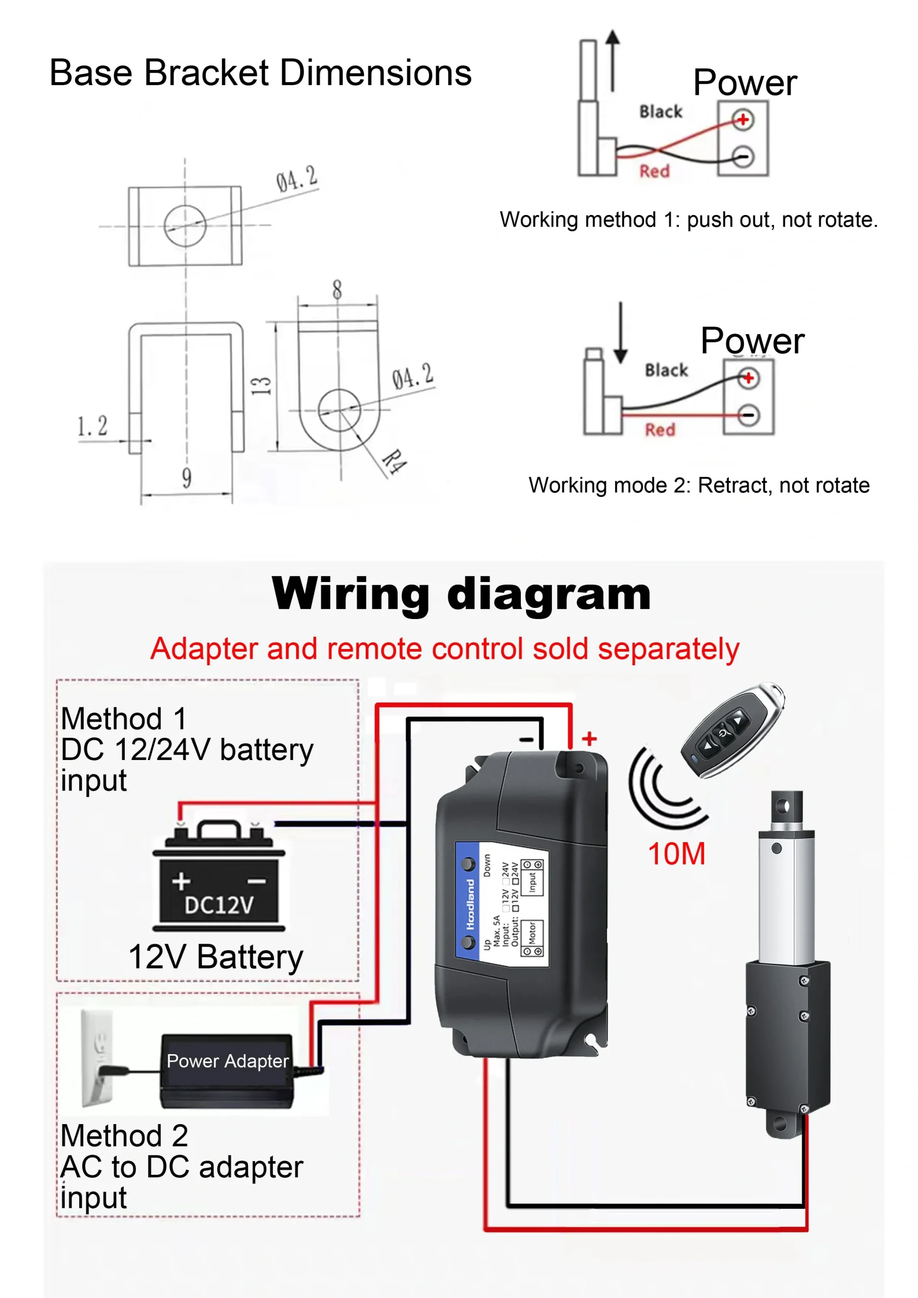
Untuk aktuator linier DC, polaritas yang benar sangat penting. Polaritas terbalik dapat menyebabkan aktuator berputar terbalik, yang berpotensi menimbulkan bahaya keselamatan dalam aplikasi Anda. Dalam beberapa kasus, pembalikan polaritas juga dapat merusak elektronik kontrol.
Rekomendasi untuk Operasi yang Aman
Selalu periksa peringkat tegangan. sebelum menyambungkan daya
Gunakan catu daya yang sesuai. dengan pengaturan tegangan yang tepat
Sertakan fusi yang sesuai untuk melindungi dari kondisi kesalahan
Provide surge/transient protection where required by the power architecture and installation environment
Ikuti pedoman instalasi produsen dengan tepat
Commission within the documented supply range and follow current-limit and test requirements for the selected product
Membuat Pilihan Anda: Kerangka Keputusan Praktis
Memilih antara aktuator linier 12V dan 24V tidak perlu rumit. Pertimbangkan kerangka keputusan ini:
Evaluate 12V when:
The equipment already provides a compatible, regulated 12V architecture
Calculated voltage drop and conductor heating are acceptable for the actual harness
The selected 12V configuration meets the required load and holding conditions
The selected 12V configuration meets the required speed under load
Power-supply, controller, wiring and lifecycle tradeoffs have been compared for the project
The controller and power source are sized for the actuator’s rated and peak current
Environmental, mounting and safety requirements remain within the selected product’s documented limits
Evaluate 24V when:
The equipment already provides a compatible 24V power architecture
Lower current at similar power helps the calculated harness/voltage-drop design
The selected 24V configuration—not the voltage label—meets the required load and duty cycle
The selected 24V configuration meets the required speed at the real load
The chosen multi-actuator controller/feedback architecture is compatible and validated
The motor driver and PLC/controller interfaces are explicitly compatible
The selected actuator has a documented duty/thermal rating that matches the operating cycle
Dapatkah saya menjalankan aktuator linier 12V pada catu daya 24V?
Do not do so unless the actuator or its approved controller documentation explicitly allows that supply range. Use the rated supply and protection requirements for the selected configuration; overvoltage can damage the motor or integrated electronics.
Apakah aktuator 24V memberikan gaya dorong lebih besar daripada versi 12V?
Not inherently. Force depends on the complete actuator design and selected configuration, including motor, gearing, screw, current limits and duty cycle. Compare the approved load specification for the exact 12V or 24V build.
Does 24V always permit longer cable runs?
No fixed distance follows from voltage alone. At the same electrical power and conductor resistance, 24V can reduce current and I²R loss, but the allowable run must be calculated from actual rated/peak current, wire size, round-trip resistance, connectors and permitted voltage drop.
When does 12V make sense for battery-powered equipment?
12V can simplify integration when the equipment already has a compatible 12V battery or regulated supply and can provide the actuator’s rated/peak current. Confirm real battery voltage range, charging conditions, transients, controller compatibility and wiring rather than assuming every vehicle or battery system is equivalent.
Kesimpulan
Choose 12V or 24V from the complete electrical and mechanical architecture. Voltage affects current and voltage-drop planning, but the selected actuator’s load, speed, duty cycle, controls, feedback, environment and mounting determine whether the configuration fits the application.
Use current 12V actuator product evidence when the equipment uses a compatible 12V architecture. Do not infer automotive, marine, battery or reliability suitability from voltage alone.
Use current 24V actuator product evidence when a 24V architecture fits the power and control design. Do not infer higher performance, longer cable capability, synchronization accuracy or PLC compatibility from the voltage label alone.
Keep the fundamental relationship: . Memahami hubungan ini membantu Anda menghargai mengapa pemilihan tegangan mempengaruhi tidak hanya kinerja, tetapi juga desain sistem, efisiensi, dan keandalan jangka panjang. Dengan mencocokkan pemilihan tegangan Anda dengan kebutuhan aplikasi, Anda akan mencapai hasil optimal dan menghindari jebakan umum yang muncul dari sistem yang tidak cocok.. Apply it with the actual actuator current, harness resistance, controller limits and working conditions. Final performance and reliability require configuration-specific validation.
For a project review, provide the required load, stroke, speed, duty cycle, available supply, cable length, controller/feedback, mounting and environment so suitable 12V or 24V candidate configurations can be compared.
Dapatkan Pandangan Para Ahli tentang Kontrol Gerakan Industri
Memilih yang tepat aktuator linier listrik atau kolom pengangkat sangat penting untuk kinerja proyek Anda. Sebagai seorang profesional Produsen Kontrol Gerakan & Otomatisasi, insinyur kami membantu Anda menyesuaikan kapasitas beban, panjang langkah, dan rating IP berdasarkan aplikasi spesifik Anda. Bagikan persyaratan teknis Anda untuk solusi yang disesuaikan.
ActuLift mendukung kustomisasi dari awal hingga akhir, mulai dari desain struktural dan parameter jalur hingga branding dan penyelesaian casing, membantu Anda membangun identitas merek yang kuat.
Respons Cepat & Prototyping
Kami memahami pentingnya kecepatan dalam pengadaan B2B, memanfaatkan alur kerja produksi yang dioptimalkan untuk memastikan respons efisien dari pengembangan sampel hingga pengiriman massal.
Quality Documentation & Traceability
Quality and traceability requirements vary by project. Ask ActuLift for the applicable inspection records, product specifications, drawings and available compliance documentation for the selected model and order.