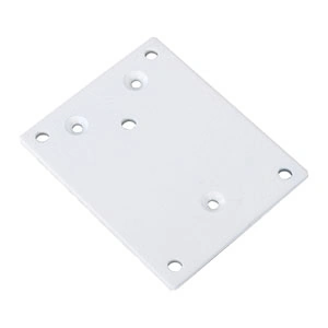
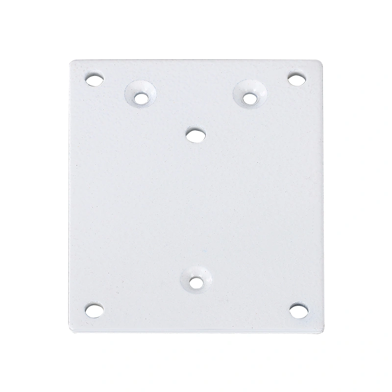
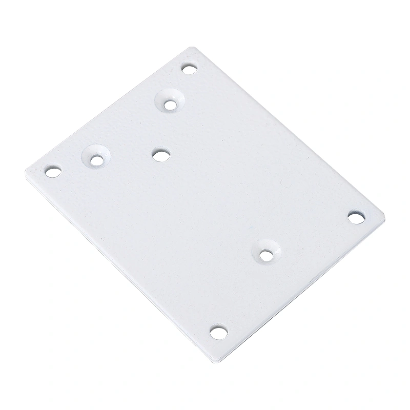
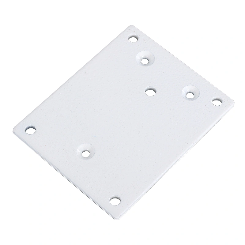
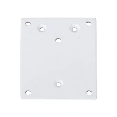
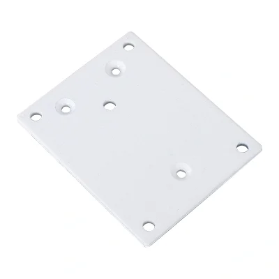
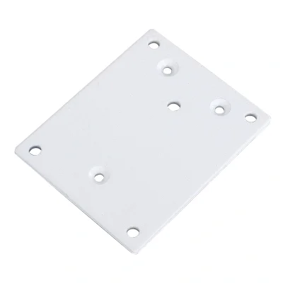
Suporte para atuador com base plana de eixo para montagens OEM
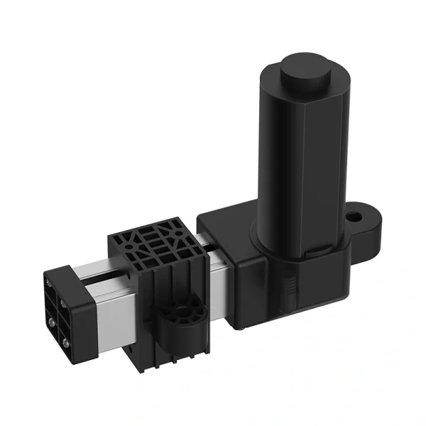
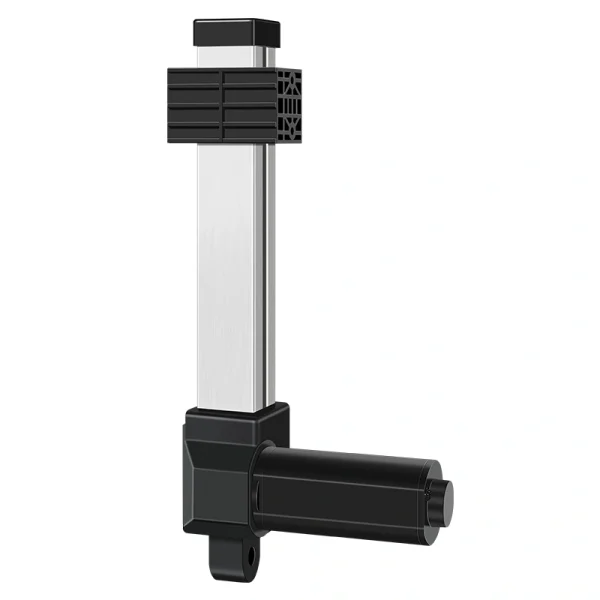
The Push Rod Flat Base Actuator Bracket is a mechanical mounting accessory for electric linear-actuator assemblies. Final fit depends on the selected actuator interface, bracket drawing, mounting-hole geometry, fasteners, load path, mounting surface and full-motion clearance.
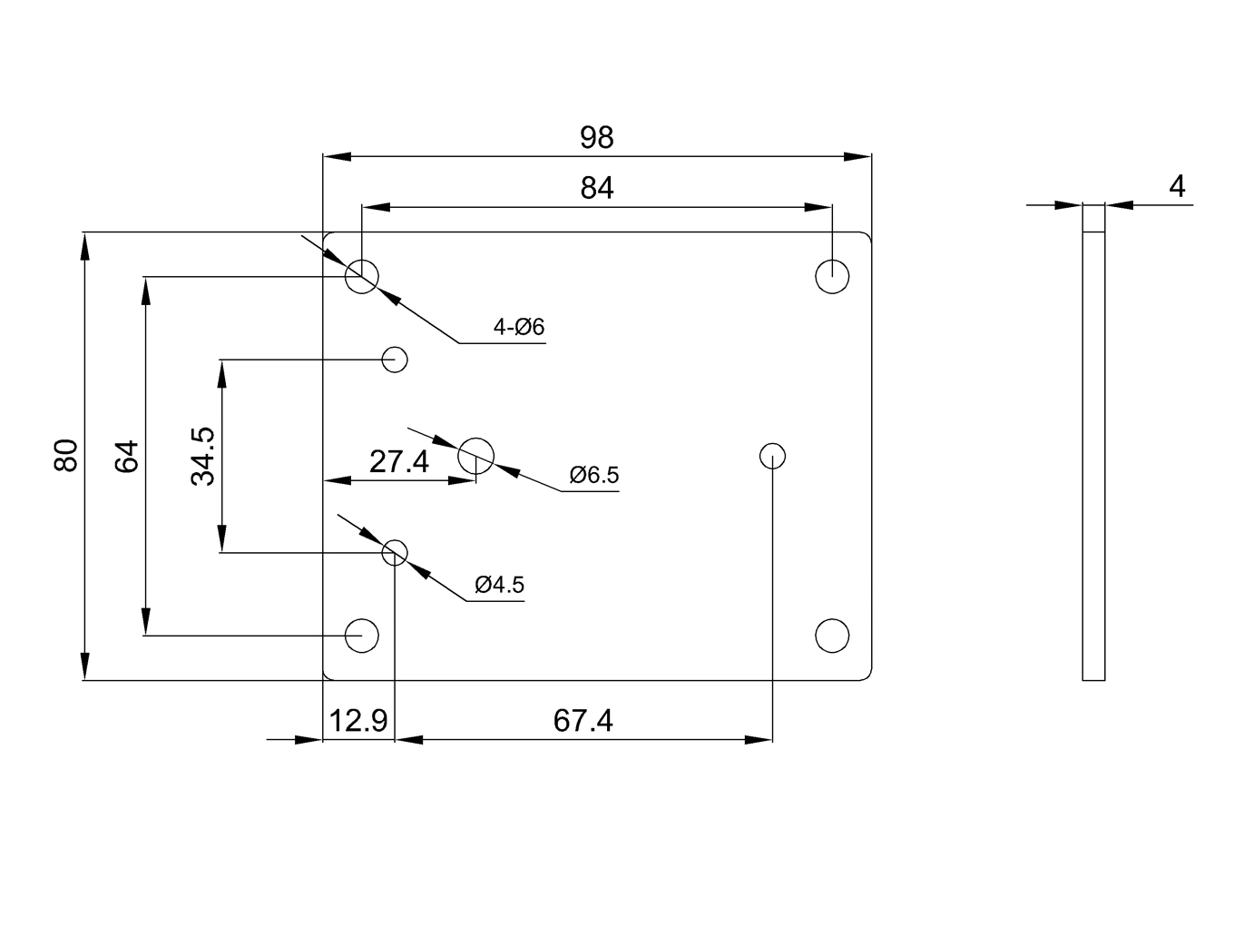
For B2B buyers, start with the exact drawing rather than a catalog dimension alone. Confirm overall length, hole diameter and spacing, bracket thickness, actuator interface and frame geometry for the selected bracket before the purchase order moves forward.
The current brief references formed carbon steel, a 4mm gauge, ASTM A36-equivalent wording, powder coating and zinc plating. Treat those as unverified catalog references until the selected bracket drawing, material record and finish specification confirm them. The current brief references IP1200, IP3000, IP800, IP40 and IP42 series applications. Confirm the exact actuator model, base interface, hole pattern, fasteners and clearance rather than assuming family-level compatibility. For teams sourcing Soluções Personalizadas OEM/ODM junto com atuadores, se encaixa naturalmente em uma lista de materiais completa de atuadores.
Especificações do produto
| Especificação | Detalhes |
|---|
| Nome do produto | Suporte para Atuador com Base Plana de Eixo |
| Capacidade máxima de carga | Confirm material grade and thickness on the selected drawing or material record. |
| Grau estrutural | Current brief references 4mm / ASTM A36-equivalent wording; confirm against the selected drawing and material documentation. |
| Padrão de furos de montagem | Current brief references 4 x Ø6mm / 84mm spacing; confirm the exact hole pattern on the selected drawing. |
| Comprimento total | Current brief references 98mm; confirm the exact overall length on the selected drawing. |
| Acabamento da superfície | Confirm available finish/coating or plating options for the selected order. |
| Suporte de carga | Do not infer load support from actuator family alone; confirm allowable bracket/assembly load for the actual geometry and load path. |
| Compatibilidade | Current brief references IP1200, IP800, IP40 and IP42; confirm exact actuator fit on the selected drawings. |
| Nota adicional de compatibilidade | Current brief also references IP3000 variants; verify the exact actuator interface, hole spacing and clearance before approval. |
| Fabricado conforme ISO 9001 | Request applicable supplier quality-system and order-specific material/finish documentation where required. |
| Atributo de variação 1 | Surface Finish: confirm available coating/plating options for the selected order |
| Atributo de variação 2 | Compatibility: confirm exact actuator model and bracket drawing |
| Atributo de variação 3 | OEM system requirement: Hall/feedback belongs to the actuator/control system, not the passive bracket; confirm separately |
Acabamentos, compatibilidade e opções OEM
If a particular coating, plating or color is required, confirm which finish is actually available for the selected order and specify appearance, corrosion exposure and coating requirements before sample approval. Do not infer corrosion performance from finish terminology alone.
Compatibility should be selected by actuator series, not by guesswork. The current brief references IP1200, IP3000, IP800, IP40 and IP42 projects, but fit must be verified against the exact actuator and bracket drawings. If you are building around atuadores lineares de alta resistência, the IP3000 compatibility option is the important one to confirm early. Do not treat an IP3000 family reference as proof of fit or load capacity. Confirm the exact actuator model, mounting interface, load direction, fasteners, bracket geometry and clearance.
The bracket is a passive mechanical component and does not itself provide Hall feedback. If the OEM system requires Hall sensors or other position feedback, specify that requirement on the actuator/controller package separately. If your project needs position feedback, synchronized movement, or controller-based travel logic, pair the bracket discussion with atuadores com feedback/controlador e o apropriado control boxes and controllers.
O que os compradores devem confirmar antes de fazer o pedido
Start with the drawing. The current brief references 98mm overall length and a 4 x Ø6mm pattern with 84mm spacing, but those dimensions should not be released as production dimensions without the selected drawing. If the frame already has fixed holes, verify the exact bracket dimensions before ordering samples.
Next, check the load path. Allowable bracket and assembly load depend on bracket geometry and material, fasteners, mounting surface, force direction, pivot or alignment conditions and the equipment frame. Confirm the actual load case rather than inheriting a load assumption from the actuator series.
Depois, verifique o pacote do atuador. Se você estiver adquirindo atuadores lineares de 12V ou atuadores lineares de 24V, o suporte ainda precisa corresponder à série mecânica e ao estilo de montagem. Apenas a voltagem não determina a adequação do suporte. A ordem prática é modelo do atuador primeiro, compatibilidade do suporte em segundo lugar, acabamento e opções de OEM em terceiro.
Notas de aquisição para compradores atacadistas e de OEM
This is a small part, but a mismatch in hole spacing, plate thickness, actuator interface, finish or load path can still cause rework. For sample orders, request the selected actuator model, bracket drawing, material/finish requirements and any actuator-side feedback requirement in the same quotation thread.
Para pedidos em grande quantidade, mantenha os nomes das variações organizados no arquivo de compra:
| Atributo | Valores |
|---|
| Revestimento em pó preto / Galvanização | Confirm available finish/coating or plating options for the selected order. |
| Compatibilidade | Confirm exact actuator model and bracket drawing |
| Personalização de OEM (Opcional) | Bracket: passive mechanical part; confirm any Hall/feedback requirement on the actuator/control system separately |
Essa estrutura ajuda o fornecedor a cotar o suporte como parte de um conjunto completo de atuadores, em vez de tratá-lo como uma parte metálica isolada. Também fornece à sua equipe de montagem notas de recebimento mais claras quando suportes, atuadores, controladores e cabos chegam juntos.
Por que este produto funciona bem
The Push Rod Flat Base Actuator Bracket is an OEM mounting accessory whose final suitability depends on the selected actuator interface, approved bracket drawing, material and finish, hole pattern, fasteners, load path, mounting surface and any documentation required for the ordered configuration.
Links internos utilizados
- Soluções Personalizadas OEM/ODM
- atuadores lineares de alta resistência
- atuadores com feedback/controlador
- control boxes and controllers
- atuadores lineares de 12V
- atuadores lineares de 24V