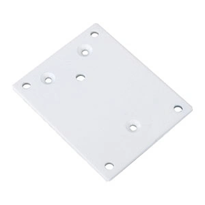
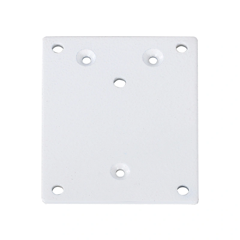
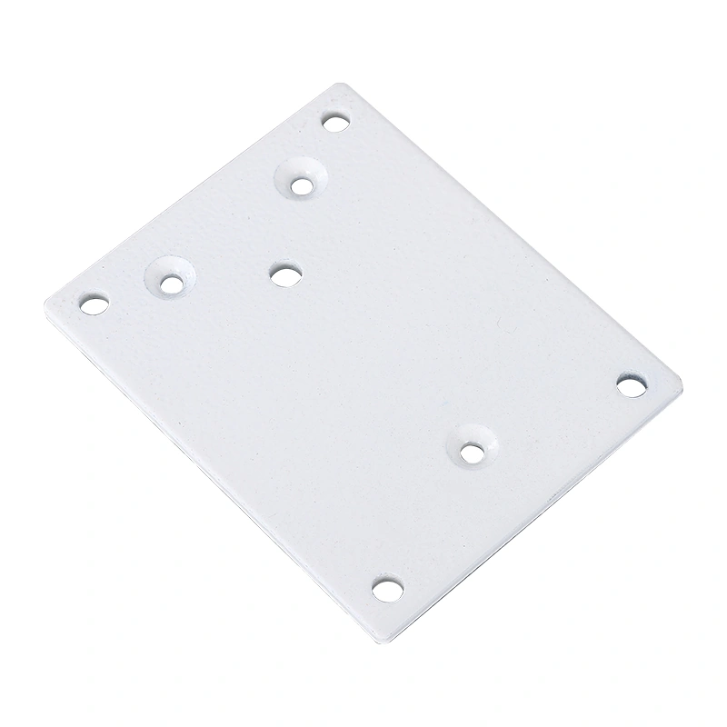
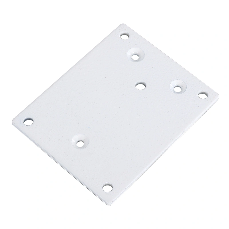
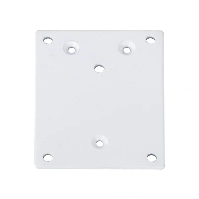
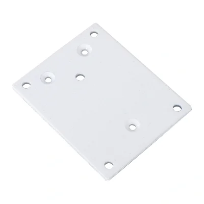
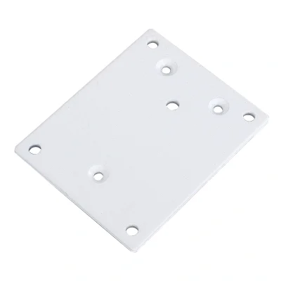
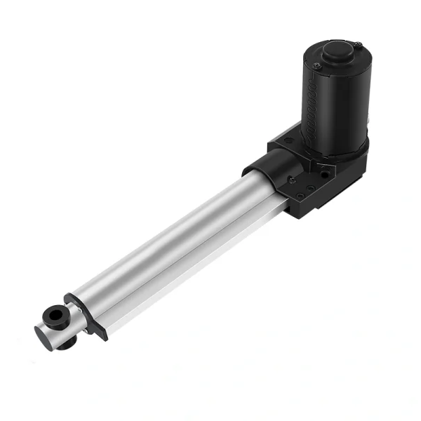
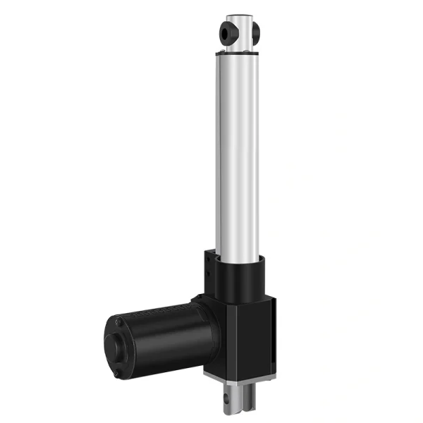
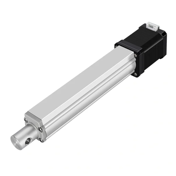
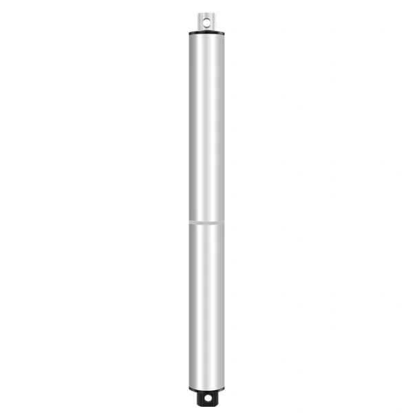
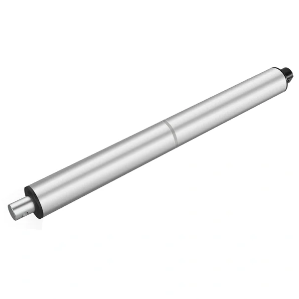
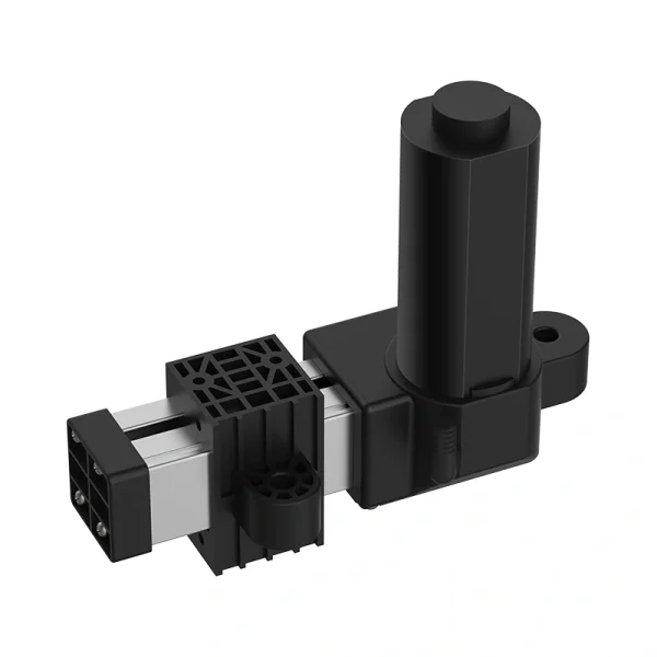
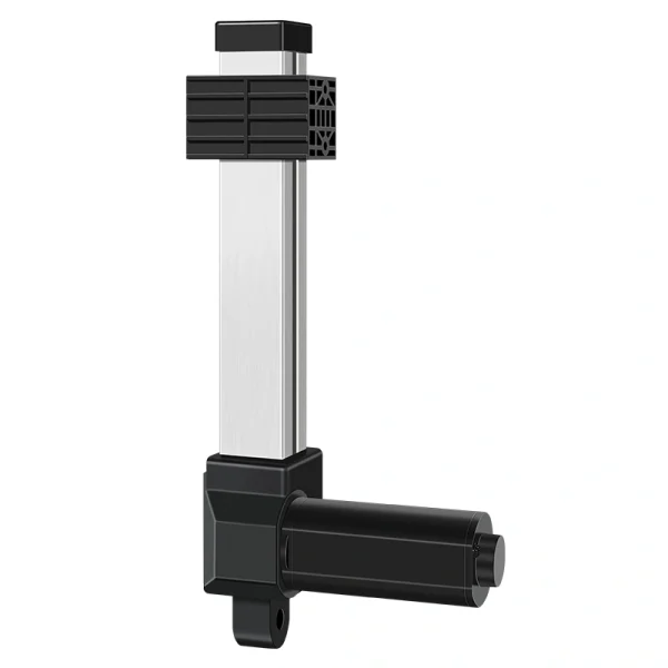
Support de vérin à plat avec base pour montages OEM
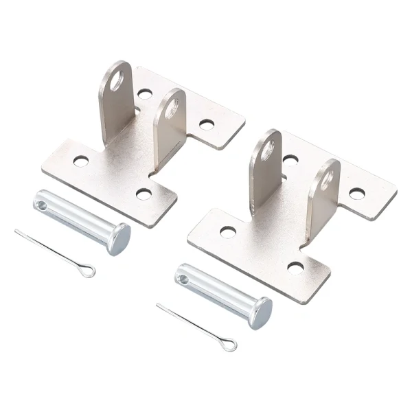
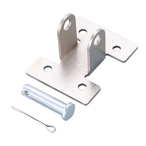
The Push Rod Flat Base Actuator Bracket is a mechanical mounting accessory for electric linear-actuator assemblies. Final fit depends on the selected actuator interface, bracket drawing, mounting-hole geometry, fasteners, load path, mounting surface and full-motion clearance.
For B2B buyers, start with the exact drawing rather than a catalog dimension alone. Confirm overall length, hole diameter and spacing, bracket thickness, actuator interface and frame geometry for the selected bracket before the purchase order moves forward.
The current brief references formed carbon steel, a 4mm gauge, ASTM A36-equivalent wording, powder coating and zinc plating. Treat those as unverified catalog references until the selected bracket drawing, material record and finish specification confirm them. The current brief references IP1200, IP3000, IP800, IP40 and IP42 series applications. Confirm the exact actuator model, base interface, hole pattern, fasteners and clearance rather than assuming family-level compatibility. For teams sourcing Solutions OEM/ODM sur mesure avec des vérins, il s'intègre naturellement dans une liste complète de matériel de vérin.
Specifications du produit
| Spécification | Détails |
|---|
| Nom du produit | Support de vérin à plat avec base |
| Acier au carbone à haute résistance/galvanisé | Confirm material grade and thickness on the selected drawing or material record. |
| Épaisseur structurelle | Current brief references 4mm / ASTM A36-equivalent wording; confirm against the selected drawing and material documentation. |
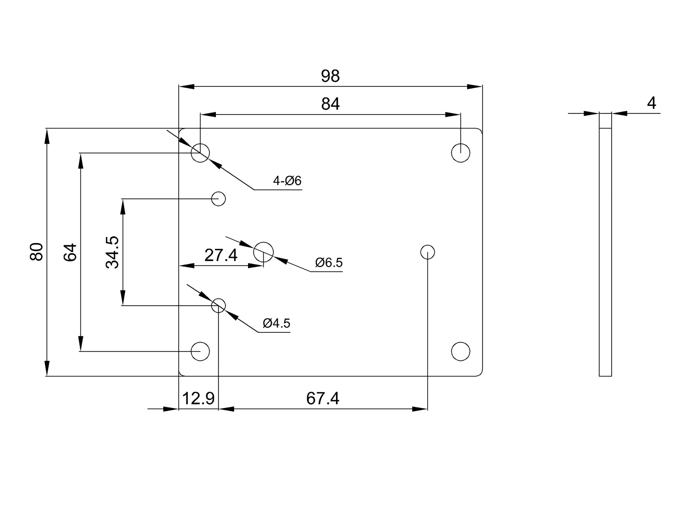
| Motif de trous de montage | Current brief references 4 x Ø6mm / 84mm spacing; confirm the exact hole pattern on the selected drawing. |
| Longueur totale | Current brief references 98mm; confirm the exact overall length on the selected drawing. |
| Finition de surface | Confirm available finish/coating or plating options for the selected order. |
| Support de charge | Do not infer load support from actuator family alone; confirm allowable bracket/assembly load for the actual geometry and load path. |
| Compatibilité | Current brief references IP1200, IP800, IP40 and IP42; confirm exact actuator fit on the selected drawings. |
| Remarque de compatibilité supplémentaire | Current brief also references IP3000 variants; verify the exact actuator interface, hole spacing and clearance before approval. |
| Certifications | Request applicable supplier quality-system and order-specific material/finish documentation where required. |
| Attribut de variation 1 | Surface Finish: confirm available coating/plating options for the selected order |
| Attribut de variation 2 | Compatibility: confirm exact actuator model and bracket drawing |
| Attribut de variation 3 | OEM system requirement: Hall/feedback belongs to the actuator/control system, not the passive bracket; confirm separately |
Finitions, compatibilité et options OEM
If a particular coating, plating or color is required, confirm which finish is actually available for the selected order and specify appearance, corrosion exposure and coating requirements before sample approval. Do not infer corrosion performance from finish terminology alone.
Compatibility should be selected by actuator series, not by guesswork. The current brief references IP1200, IP3000, IP800, IP40 and IP42 projects, but fit must be verified against the exact actuator and bracket drawings. If you are building around actionneurs linéaires lourds, the IP3000 compatibility option is the important one to confirm early. Do not treat an IP3000 family reference as proof of fit or load capacity. Confirm the exact actuator model, mounting interface, load direction, fasteners, bracket geometry and clearance.
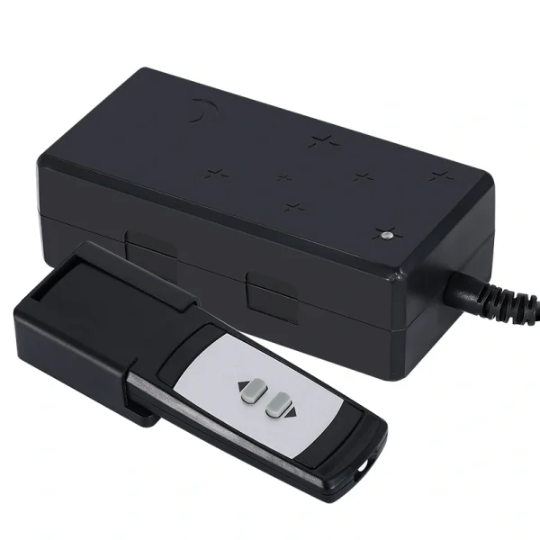
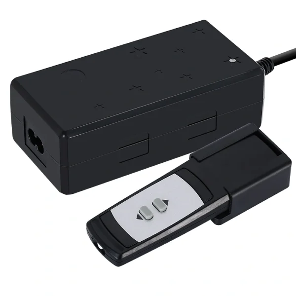
The bracket is a passive mechanical component and does not itself provide Hall feedback. If the OEM system requires Hall sensors or other position feedback, specify that requirement on the actuator/controller package separately. If your project needs position feedback, synchronized movement, or controller-based travel logic, pair the bracket discussion with actionneurs avec retour d'information / contrôleur et le bon control boxes and controllers.
Ce que les acheteurs devraient confirmer avant de commander
Start with the drawing. The current brief references 98mm overall length and a 4 x Ø6mm pattern with 84mm spacing, but those dimensions should not be released as production dimensions without the selected drawing. If the frame already has fixed holes, verify the exact bracket dimensions before ordering samples.
Next, check the load path. Allowable bracket and assembly load depend on bracket geometry and material, fasteners, mounting surface, force direction, pivot or alignment conditions and the equipment frame. Confirm the actual load case rather than inheriting a load assumption from the actuator series.
Puis vérifiez le package de l'actionneur. Si vous vous approvisionnez actionneurs linéaires 12V ou actionneurs linéaires 24V, le support doit toujours correspondre à la série mécanique et au style de montage. La tension seule ne détermine pas l'adéquation du support. L'ordre pratique est le modèle d'actionneur en premier, la compatibilité du support en second, les finitions et les options OEM en troisième.
Notes d'approvisionnement pour les acheteurs en gros et OEM
This is a small part, but a mismatch in hole spacing, plate thickness, actuator interface, finish or load path can still cause rework. For sample orders, request the selected actuator model, bracket drawing, material/finish requirements and any actuator-side feedback requirement in the same quotation thread.
Pour les commandes en gros, gardez les noms de variations clairs dans le fichier d'achat :
| Attribut | Valeurs |
|---|
| Finition de Surface | Confirm available finish/coating or plating options for the selected order. |
| Compatibilité | Confirm exact actuator model and bracket drawing |
| Personnalisation OEM (optionnelle) | Bracket: passive mechanical part; confirm any Hall/feedback requirement on the actuator/control system separately |
Cette structure aide le fournisseur à établir un devis pour le support dans le cadre d'un ensemble complet d'actionneurs au lieu de le traiter comme une pièce métallique isolée. Cela fournit également à votre équipe d'assemblage des notes de réception plus claires lorsque les supports, les actionneurs, les contrôleurs et les câbles arrivent ensemble.
Pourquoi ce produit fonctionne bien
The Push Rod Flat Base Actuator Bracket is an OEM mounting accessory whose final suitability depends on the selected actuator interface, approved bracket drawing, material and finish, hole pattern, fasteners, load path, mounting surface and any documentation required for the ordered configuration.
Liens internes utilisés
- Solutions OEM/ODM sur mesure
- actionneurs linéaires lourds
- actionneurs avec retour d'information / contrôleur
- control boxes and controllers
- actionneurs linéaires 12V
- actionneurs linéaires 24V