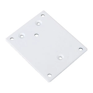
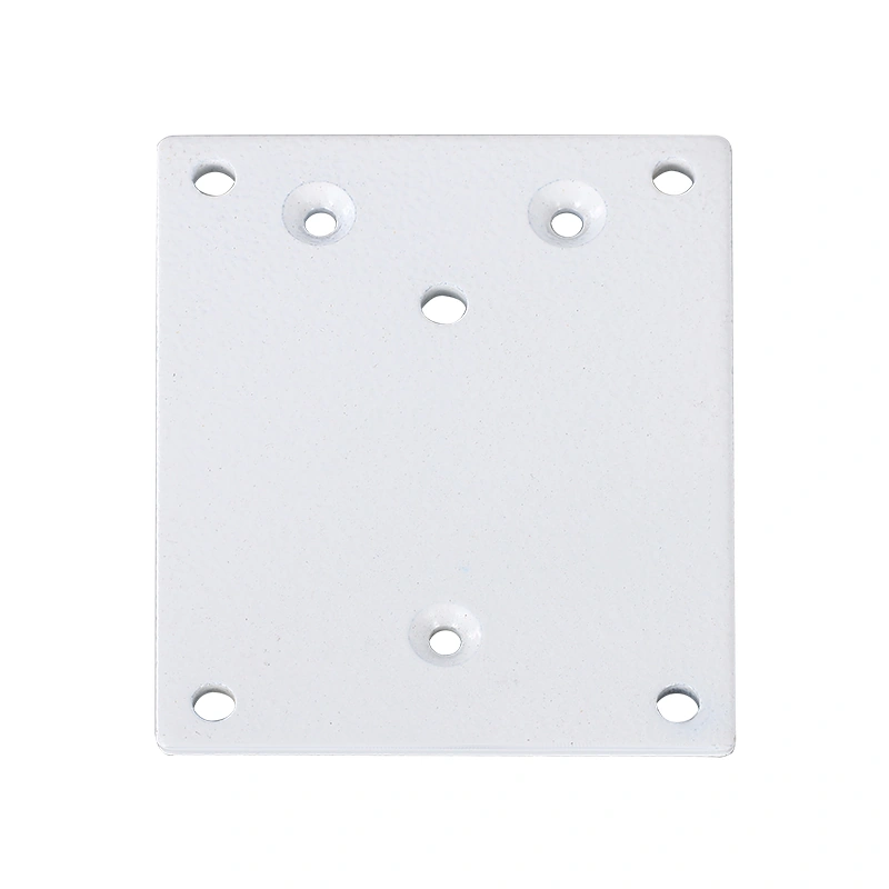
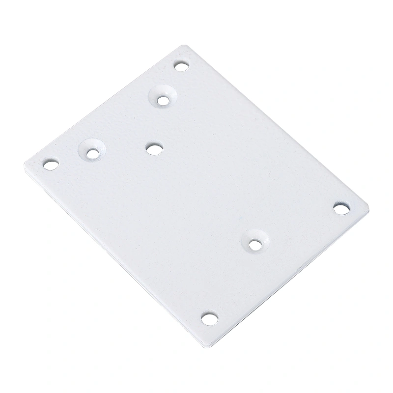
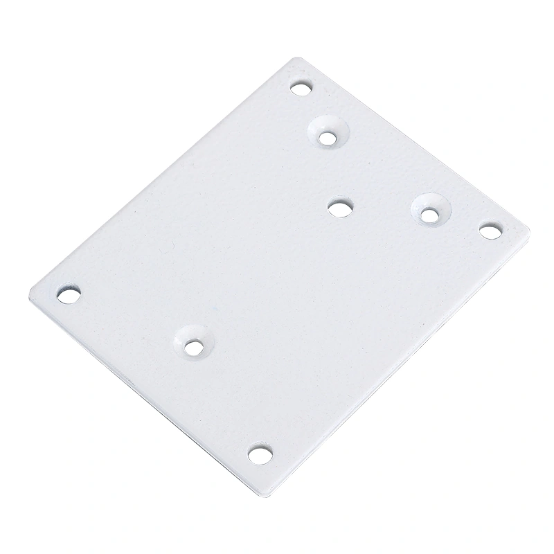
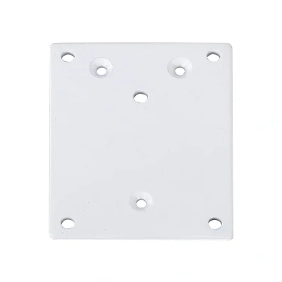
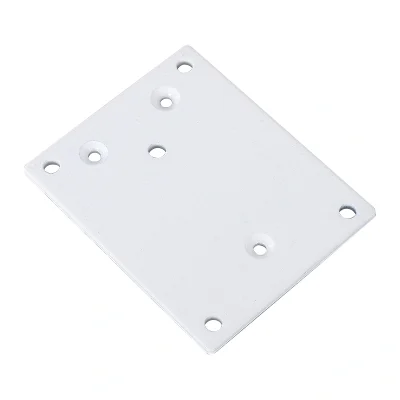
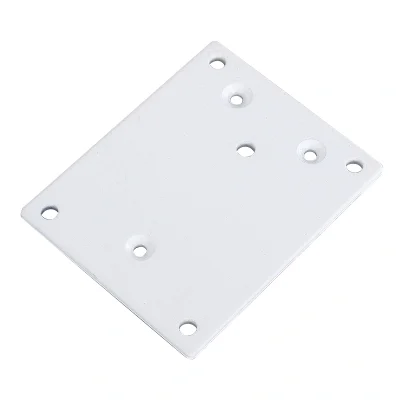
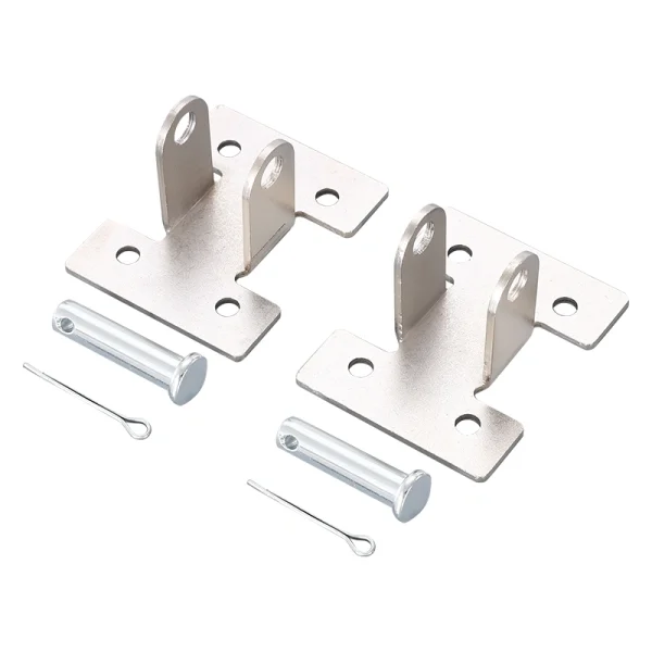
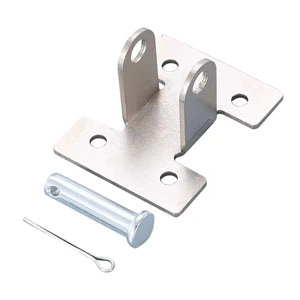
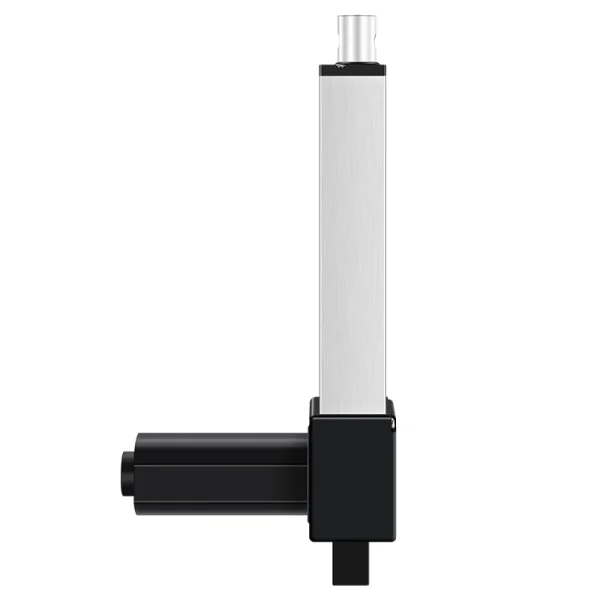
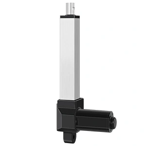
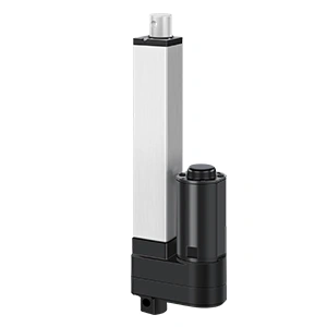
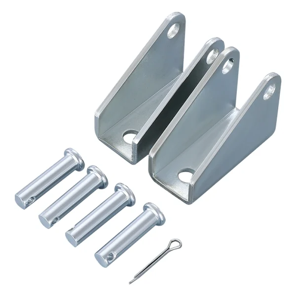
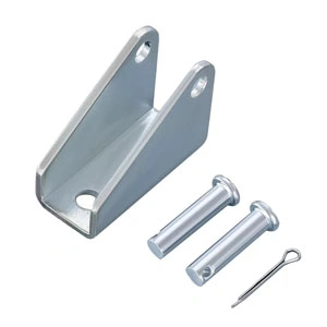
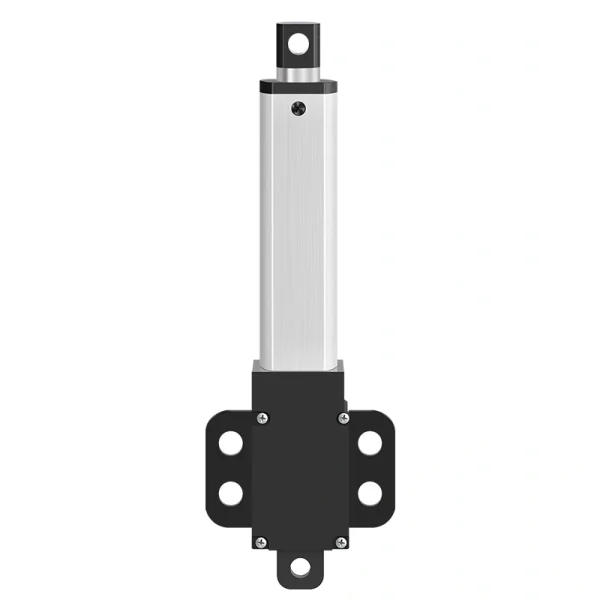
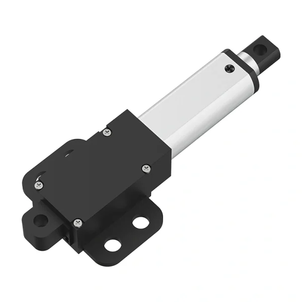
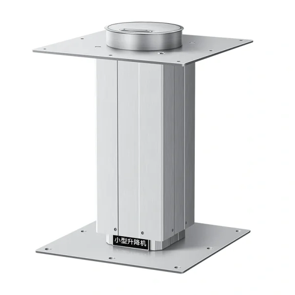
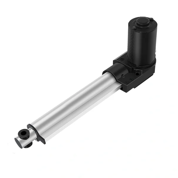
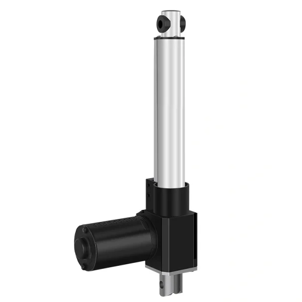
Soporte de actuador de base plana para varilla de empuje para construcciones de montaje OEM
The Push Rod Flat Base Actuator Bracket is a mechanical mounting accessory for electric linear-actuator assemblies. Final fit depends on the selected actuator interface, bracket drawing, mounting-hole geometry, fasteners, load path, mounting surface and full-motion clearance.
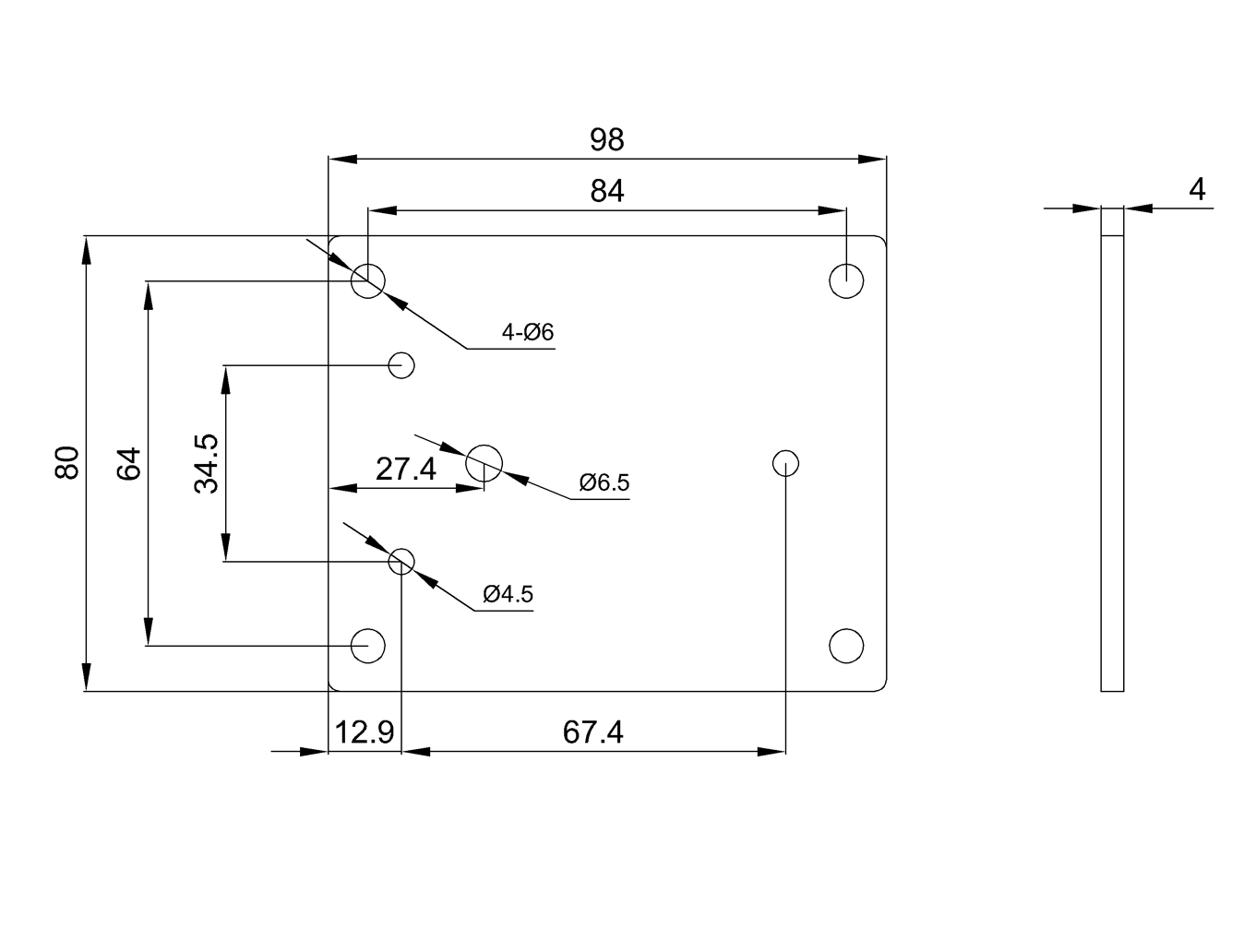
For B2B buyers, start with the exact drawing rather than a catalog dimension alone. Confirm overall length, hole diameter and spacing, bracket thickness, actuator interface and frame geometry for the selected bracket before the purchase order moves forward.
The current brief references formed carbon steel, a 4mm gauge, ASTM A36-equivalent wording, powder coating and zinc plating. Treat those as unverified catalog references until the selected bracket drawing, material record and finish specification confirm them. The current brief references IP1200, IP3000, IP800, IP40 and IP42 series applications. Confirm the exact actuator model, base interface, hole pattern, fasteners and clearance rather than assuming family-level compatibility. For teams sourcing — Ingeniería de movimiento a medida para junto con actuadores, encaja naturalmente en una lista completa de materiales de actuador.
Especificaciones del producto
| Especificación | Detalles |
|---|
| Nombre del producto | Soporte de Actuador de Base Plana para Varilla de Empuje |
| Material composition | Confirm material grade and thickness on the selected drawing or material record. |
| Calibre estructural | Current brief references 4mm / ASTM A36-equivalent wording; confirm against the selected drawing and material documentation. |
| Patrón de agujeros de montaje | Current brief references 4 x Ø6mm / 84mm spacing; confirm the exact hole pattern on the selected drawing. |
| Longitud total | Current brief references 98mm; confirm the exact overall length on the selected drawing. |
| Acabado de superficie | Confirm available finish/coating or plating options for the selected order. |
| Soporte de carga | Do not infer load support from actuator family alone; confirm allowable bracket/assembly load for the actual geometry and load path. |
| Compatibilidad | Current brief references IP1200, IP800, IP40 and IP42; confirm exact actuator fit on the selected drawings. |
| Nota de compatibilidad adicional | Current brief also references IP3000 variants; verify the exact actuator interface, hole spacing and clearance before approval. |
| Manufacturado según ISO 9001 | Request applicable supplier quality-system and order-specific material/finish documentation where required. |
| Atributo de variación 1 | Surface Finish: confirm available coating/plating options for the selected order |
| Atributo de variación 2 | Compatibility: confirm exact actuator model and bracket drawing |
| Atributo de variación 3 | OEM system requirement: Hall/feedback belongs to the actuator/control system, not the passive bracket; confirm separately |
Opciones de acabado, compatibilidad y OEM
If a particular coating, plating or color is required, confirm which finish is actually available for the selected order and specify appearance, corrosion exposure and coating requirements before sample approval. Do not infer corrosion performance from finish terminology alone.
Compatibility should be selected by actuator series, not by guesswork. The current brief references IP1200, IP3000, IP800, IP40 and IP42 projects, but fit must be verified against the exact actuator and bracket drawings. If you are building around actuadores lineales de alta resistencia, the IP3000 compatibility option is the important one to confirm early. Do not treat an IP3000 family reference as proof of fit or load capacity. Confirm the exact actuator model, mounting interface, load direction, fasteners, bracket geometry and clearance.
The bracket is a passive mechanical component and does not itself provide Hall feedback. If the OEM system requires Hall sensors or other position feedback, specify that requirement on the actuator/controller package separately. If your project needs position feedback, synchronized movement, or controller-based travel logic, pair the bracket discussion with actuadores con retroalimentación/controlador y el adecuado control boxes and controllers.
Lo que los compradores deben confirmar antes de ordenar
Start with the drawing. The current brief references 98mm overall length and a 4 x Ø6mm pattern with 84mm spacing, but those dimensions should not be released as production dimensions without the selected drawing. If the frame already has fixed holes, verify the exact bracket dimensions before ordering samples.
Next, check the load path. Allowable bracket and assembly load depend on bracket geometry and material, fasteners, mounting surface, force direction, pivot or alignment conditions and the equipment frame. Confirm the actual load case rather than inheriting a load assumption from the actuator series.
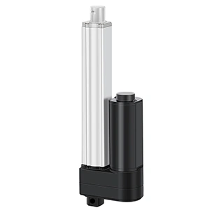
Luego revisa el paquete del actuador. Si estás adquiriendo Actuadores lineales de 12V o Actuadores lineales de 24V, el soporte aún necesita coincidir con la serie mecánica y el estilo de montaje. El voltaje por sí solo no determina la compatibilidad del soporte. El camino práctico es primero el modelo del actuador, segundo la compatibilidad del soporte, y tercero las opciones de acabado y OEM.
Notas de adquisición para compradores mayoristas y OEM
This is a small part, but a mismatch in hole spacing, plate thickness, actuator interface, finish or load path can still cause rework. For sample orders, request the selected actuator model, bracket drawing, material/finish requirements and any actuator-side feedback requirement in the same quotation thread.
Para pedidos al por mayor, mantén los nombres de las variaciones claros en el archivo de compras:
| Atributo | Valores |
|---|
| Revestimiento en Polvo Negro / Galvanizado | Confirm available finish/coating or plating options for the selected order. |
| Compatibilidad | Confirm exact actuator model and bracket drawing |
| Personalización OEM (Opcional) | Bracket: passive mechanical part; confirm any Hall/feedback requirement on the actuator/control system separately |
Esa estructura ayuda al proveedor a cotizar el soporte como parte de un conjunto completo de actuadores en lugar de tratarlo como una pieza de metal aislada. También proporciona a tu equipo de ensamblaje notas de recepción más claras cuando los soportes, actuadores, controladores y cables llegan juntos.
Por qué este producto funciona bien
The Push Rod Flat Base Actuator Bracket is an OEM mounting accessory whose final suitability depends on the selected actuator interface, approved bracket drawing, material and finish, hole pattern, fasteners, load path, mounting surface and any documentation required for the ordered configuration.
Enlaces internos utilizados
- — Ingeniería de movimiento a medida para
- actuadores lineales de alta resistencia
- actuadores con retroalimentación/controlador
- control boxes and controllers
- Actuadores lineales de 12V
- Actuadores lineales de 24V