The Danger of Side Loads on Linear Actuators: How to Prevent Mechanical Failure
Prevent premature mechanical failure in your linear systems. This expert guide explains the physics of "side loads" and "static bending moments," detailing how lateral forces damage internal bearings and screws, and providing 5 essential installation best practices to extend your actuator’s lifespan.
Learn how to prevent mechanical failure in linear actuators caused by side loads. Expert installation tips to protect your equipment and extend actuator lifespan.
Table of Contents
Introduction
If you’ve ever installed a linear actuator only to hear an unexpected hum, feel unusual vibration, or notice premature wear, there’s a good chance you encountered a problem that plagues countless engineers and equipment designers: side load.
The warning appears in product manuals across the industry, often buried in technical specifications: “Static Bending Moment: Side loads are not permitted.” It’s a clear statement—but what does it actually mean for your installation? More importantly, what happens when you ignore it?
Side loads represent one of the most common causes of linear actuator failure in industrial and commercial applications. Unlike axial loads (force applied along the actuator’s primary axis), side loads exert lateral pressure on the actuator’s internal components, creating bending moments that the unit was never designed to handle. The result? Shortened lifespan, reduced performance, and potentially catastrophic mechanical failure at the worst possible moment.
In this guide, we’ll break down what side loads are, why they’re so dangerous, the engineering principles behind the static bending moment warning, and—most importantly—how to properly install your linear actuators to avoid these problems entirely.
Understanding Side Loads: The Engineering Fundamentals
What Is a Side Load?
A side load (also called lateral load) is any force applied perpendicular to the primary axis of motion of a linear actuator. While linear actuators are engineered to handle substantial thrust and pull forces along their length—often ranging from hundreds to thousands of newtons—they possess minimal capacity for forces acting sideways.
When you push or pull on the end of an actuator at an angle rather than directly along its stroke axis, you’re introducing a side load. This creates a bending moment—a force that causes the actuator housing and internal components to flex under pressure.
What Is Static Bending Moment?
The term static bending moment refers to the rotational force created when a lateral load is applied at a distance from a reference point (in this case, the actuator’s mounting flange). Mathematically, it’s calculated as:
Bending Moment = Force × Distance
Even relatively small side loads can generate significant bending moments if they act at a distance from the mounting point. For example, a 50N side load applied 100mm from the actuator’s mounting flange creates a 5Nm bending moment—a force that can quickly overwhelm the actuator’s structural limits.
The product specification warning “Side loads are not permitted” isn’t arbitrary. It’s the manufacturer’s way of telling you that the actuator’s bearings, housing, screw mechanism, and motor were designed exclusively for axial loading. Any deviation from this creates stress concentrations that lead to:
Premature bearing wear: The internal bearings are designed for radial loads, not lateral ones
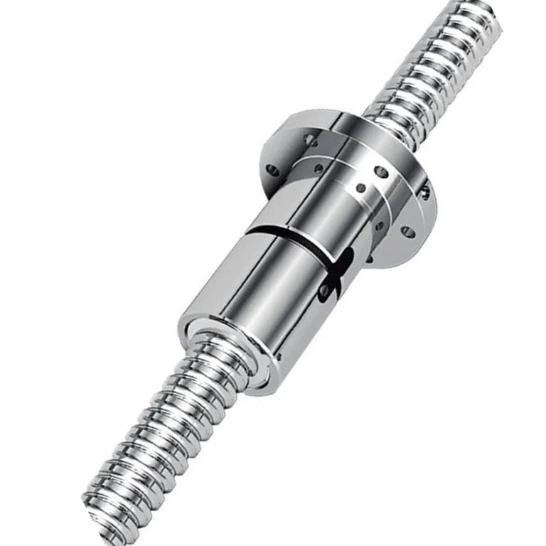
Screw thread degradation: The lead screw or ball screw experiences uneven loading
Housing fatigue: Metal fatigue accelerates cracks and structural failure
Motor strain: The motor works harder to compensate for misalignment, leading to overheating
Why Side Loads Cause Failure: A Closer Look at the Mechanics
The Problem with Misalignment
When a linear actuator operates under side load conditions, several things happen inside the unit:
Bearing overload: The internal bearings experience uneven pressure distribution. Instead of load being spread evenly across the bearing race, it concentrates at one point, dramatically accelerating wear.
Screw mechanism stress: In actuators with lead screws or ball screws, side loads cause the thread engagement to become uneven. This leads to thread deformation, increased friction, and eventual failure.
Seal damage: The rod seal and wiper seal designed to keep contaminants out become compromised when the rod is forced to move under lateral stress. This allows dirt and moisture ingress, causing internal corrosion and further degradation.
Increased power consumption: The motor must work against additional resistance, drawing more current, generating more heat, and reducing overall efficiency.
Real-World Consequences
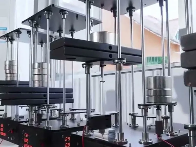
Consider a typical industrial application: a factory floor where heavy duty linear actuators operate automated machinery. A maintenance technician mounts an actuator to position a conveyor belt component but fails to align the mounting points perfectly. Over weeks of operation, the misalignment introduces a continuous side load.
Within months, the actuator begins exhibiting symptoms:
This scenario repeats across industries every day—and it’s almost entirely preventable with proper installation practices.
How to Prevent Side Load Damage: Installation Best Practices
The good news: preventing side load damage is largely a matter of proper installation technique. Here’s how to protect your linear actuators:
1. Ensure Perfect Axis Alignment
The single most important factor is aligning the actuator’s axis with the direction of motion. The load path must be straight and parallel to the actuator’s stroke.
Use precision mounting hardware
Check alignment with levels and straightedges during installation
Account for thermal expansion in outdoor or high-temperature environments
2. Use Proper Mounting Brackets
Never attempt to “make do” with improvised mounting solutions. Use manufacturer-recommended brackets and mountings designed for your specific actuator model.
Quality brackets provide:
Precise shaft engagement
Built-in bearings that can handle minor misalignments
Proper load distribution across the actuator housing
3. Support the Load Properly
If your application involves any lateral movement or if the load has mass that could create side forces, incorporate additional guidance mechanisms:
Linear rails or guide shafts parallel to the actuator
Pivot mounts at both ends to allow self-alignment
Telescopic covers to maintain clean environments
4. Account for Off-Axis Forces
In real-world applications, perfect alignment isn’t always possible. Consider:
Rod-end bearings: These allow slight angular movement at the connection point
Pivot mounts: Essential when the actuator must connect to moving parts at angles
Couplings: Flexible couplings can absorb minor misalignments (though they shouldn’t be relied upon to compensate for major alignment issues)
5. Regular Inspection and Maintenance
Even with perfect initial installation, check periodically for:
Loose mounting hardware (vibration can cause fasteners to loosen)
Signs of unusual wear patterns
Changes in noise or performance that might indicate developing problems
Choosing the Right Components for Your Application
When selecting linear actuators for your project, consider the specific demands of your installation:
Application Requirements
Factor
Consideration
Load magnitude
Choose an actuator with adequate force capacity (typically 2-3× your calculated requirement)
Stroke length
Ensure sufficient stroke plus adequate mounting length
Speed requirements
Faster operations may be more sensitive to misalignment
Duty cycle
High-duty-cycle applications demand more robust installation practices
Environment
Corrosive, dusty, or high-temperature environments require additional protection
When in Doubt, Consult Experts
For complex applications in industrial automation, don’t hesitate to reach out to application engineers. They can help specify the right actuator, recommend appropriate mounting configurations, and identify potential issues before they become problems.
Can I use a linear actuator to support a heavy door opening at an angle?
Direct attachment may cause side loads as the angle changes. You must use Pivot Mountings or rod-end bearings to allow the actuator to self-align with the load path.
What is the most common sign of side load damage?
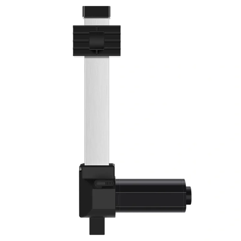
Increased noise (grinding or humming), jerky motion, and visible scoring or uneven wear on the aluminum inner tube or stainless steel rod.
How do linear rails help prevent side loads?
Linear rails act as a secondary guidance system, absorbing all lateral and moment forces so the actuator only has to handle the axial thrust it was designed for.
Conclusion: Protect Your Investment
Side loads on linear actuators represent a deceptively simple problem with serious consequences. That warning in the product manual—“Static Bending Moment: Side loads are not permitted”—isn’t a suggestion. It’s an engineering reality based on the fundamental physics of how these devices work.
The good news is that preventing side load damage is straightforward:
Design for alignment: Plan your installation to ensure axial loading
Follow manufacturer guidelines: The specifications exist for good reasons
Inspect regularly: Catch potential problems before they cause failure
By understanding the mechanics of side loads and following proper installation practices, you can dramatically extend the lifespan of your linear actuators, reduce downtime, and protect your equipment investment.
Your linear actuator is built to move loads efficiently along a single axis. Give it the installation it was designed for—and it’ll serve you reliably for years to come.
Ready to explore our full range of linear actuation solutions? Browse our collection of linear actuators and heavy duty linear actuators to find the perfect match for your application. And for standing desk applications, check out our dedicated standing desk frames solutions.
Have questions about proper actuator installation? Contact our technical team for personalized guidance.
Selecting the right electric linear actuator or lifting column is critical for your project's performance. As a professional Motion Control & Automation Manufacturer, our engineers help you customize load capacity, stroke length, and IP ratings based on your specific application. Share your technical requirements for a tailored solution.
ActuLift supports end-to-end customization, from structural design and stroke parameters to branding and casing finishes, helping you build a powerful brand identity.
Rapid Response & Prototyping
We understand the importance of speed in B2B procurement, utilizing optimized production workflows to ensure efficient responses from sample development to bulk delivery.
Stable Quality & Traceability
With ISO9001 quality assurance, every product—from material entry to final factory testing—is recorded in our electronic logs, ensuring high consistency in delivered goods.