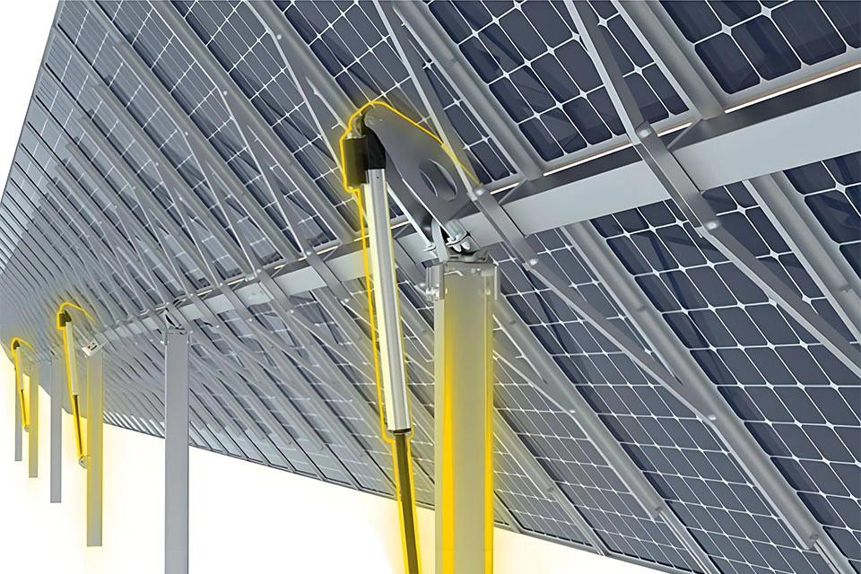
Solar trackers can increase energy capture by keeping modules closer to the intended sun angle, but real-world performance depends on the complete mechanical and control system. Actuator selection should therefore be based on verified load, holding, stroke, speed, feedback, environmental, duty-cycle and mounting requirements rather than a generic efficiency-improvement claim.
The actuator is one part of the tracker’s motion system. It influences travel, holding behavior, response under wind load, control feedback and serviceability, while the final tracking result also depends on structure, geometry, controller logic, sensors, stow strategy, commissioning and site conditions.
This article reviews the engineering questions that matter when evaluating ActuLift’s IP1200 for a solar-tracker project. It does not treat a fixed percentage gain, wind-speed limit, positioning accuracy or service-life result as universal evidence for every IP1200 configuration.
Tabela de Conteúdos
O Desafio — Por que os Rastreados Solares Desempenham Abaixo do Esperado
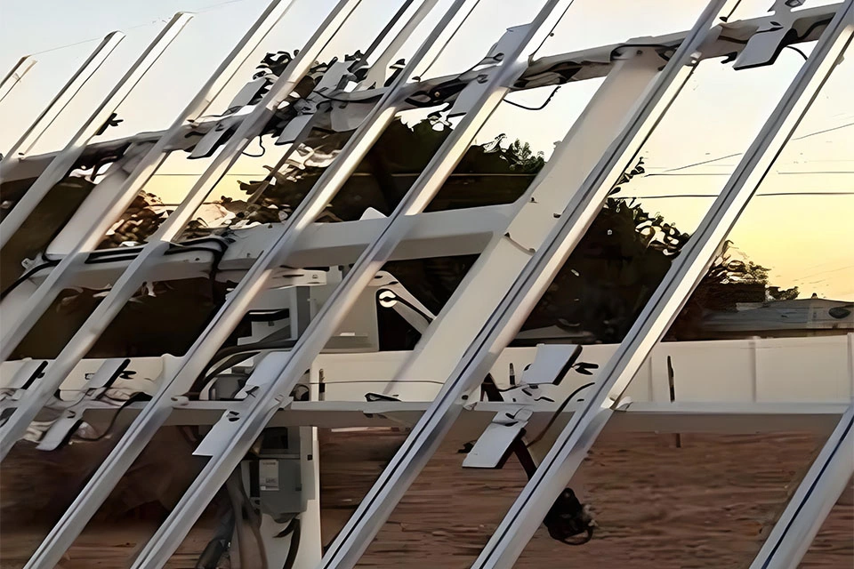
Solar tracking systems may face heat, cold, dust, rain, humidity, corrosion, wind events and repeated thermal cycling. The actual environmental envelope varies by site, so the actuator specification should be tied to the project’s temperature, ingress-protection, corrosion, cable, connector and maintenance requirements.
1. Desalinhamento Induzido pelo Vento
Wind can change the load on a tracker structure and can introduce deflection, vibration or misalignment. The effect on energy capture depends on tracker geometry, control strategy, irradiance conditions and the duration of any deviation, so a single angular or yield-loss figure should not be assumed without a project-specific model.
Holding and back-driving behavior matter when the tracker is exposed to wind or loses power. Instead of assuming that a screw type guarantees self-locking, confirm the selected actuator’s static holding requirement, gearing, orientation, friction, brake strategy and tested power-off behavior.
2. Falhas em Ambientes Severos
Outdoor actuators can be affected by temperature cycling, dust, moisture, UV exposure, corrosion and contamination. Define the site conditions first, then request configuration-specific environmental limits and ingress-protection evidence for the selected actuator, cable and connector arrangement.
Remote installations can make service events expensive because access, labor, travel, lost operating time and spare-parts logistics all contribute to lifecycle cost. Use the project’s own maintenance assumptions rather than a generic truck-roll cost when comparing actuator options.
3. Posicionamento Impreciso
Open-loop motion can accumulate error when mechanical wear, backlash, thermal expansion, structural deflection or load variation changes the relationship between commanded actuator travel and actual panel angle. The magnitude of this effect must be measured on the real tracker mechanism.
Dual-axis systems add another control dimension, so actuator feedback, sensor strategy, controller logic, mechanical geometry and calibration need to be considered together. Do not infer final tracker accuracy from an actuator feedback option alone.
4. Altos Custos de Manutenção
Environmental exposure, alignment, overload, wear, contamination, electrical faults and control issues can all increase maintenance demand. For project economics, compare expected inspection intervals, replacement strategy, accessibility, spares, diagnostic capability and configuration-specific validation data.
Evaluating IP1200 Against Solar-Tracker Requirements
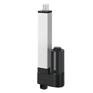
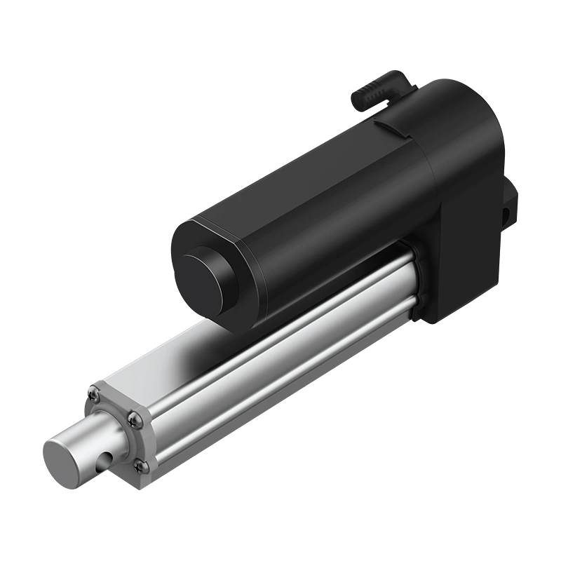
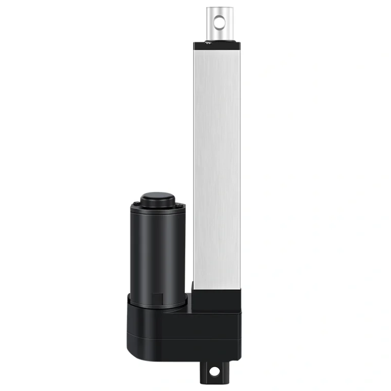
The ActuLift IP1200 is a configurable heavy-duty OEM linear-actuator platform. For solar-tracker use, evaluate the selected build against the actual load case, holding requirement, stroke, speed, control/feedback architecture, environment, duty cycle, mounting geometry and supporting documentation.
Wind Load and Holding
The current IP1200 product page no longer treats an older 2,500N-at-5mm/s figure or a 100 km/h wind statement as a universal specification. Its current brief references a working-load figure that must be confirmed for direction, duty cycle, safety factor and test conditions. Convert site wind conditions into actuator force through the tracker geometry and structural load case before selection.
Position holding is configuration-dependent. Confirm whether the selected gearing and screw arrangement resists back-driving at the required load and orientation, whether a brake or other holding mechanism is needed, and what happens during power loss or a commanded stow event.
Para integradores de sistemas que avaliam especificações de atuadores, a ActuLift fornece orientações detalhadas sobre soluções de resistência ao vento para sistemas de rastreamento solar que abrangem cálculos de carga e configurações de montagem para ambientes com alta incidência de vento.
Environmental Fit and Protection
Do not assume a universal IP54 rating from this article. Request the current ingress-protection documentation for the selected IP1200 configuration and confirm how the actuator, rod, cable, connector, mounting orientation and surrounding enclosure behave under the project’s dust, rain, washdown or condensation conditions.
Operating-temperature range, housing material, finish and corrosion resistance must also be confirmed for the ordered build. Match those limits to the site’s ambient temperature, solar heating, freeze conditions, humidity, salt exposure and maintenance regime.
CE/RoHS or other compliance statements should be supported by current model- or configuration-specific declarations and their stated scope. Component documentation does not replace the tracker manufacturer’s finished-system regulatory and market requirements.
Feedback and Positioning
IP1200 may be configured with feedback options, but Hall sensors or a 5-wire interface should not be converted into a universal 0.1° tracker-accuracy claim. Confirm the available feedback type, signal characteristics, controller compatibility, resolution, calibration method and the relationship between actuator travel and actual panel angle.
Closed-loop control can help the system detect and correct motion error, but final tracking accuracy depends on the complete mechanism, sensor placement, backlash, structural deflection, control algorithm and commissioning. Validate the finished tracker under representative loads and temperatures.
Do not assume a feedback interface is automatically compatible with every tracker controller or with both single-axis and dual-axis architectures. Confirm voltage levels, pulse or signal format, wiring, controller inputs, synchronization logic and fault handling for the selected system.
Configuration and Serviceability
The current IP1200 product page notes a brief reference to a 50–600mm stroke range, but the exact available stroke and installation dimensions still require confirmation for the selected build. Likewise, confirm voltage, connector, mounting and controller requirements instead of relying on the older 30–1000mm / dual-voltage wording in this article.
Noise and duty cycle are also configuration- and test-condition-dependent. If the project has an acoustic limit or an intermittent movement schedule, define the measurement method, load, speed, ambient conditions, run/rest pattern and worst-case thermal profile, then request applicable evidence for the selected actuator.
Mounting geometry should be confirmed from the current drawing. Verify clevis, trunnion or other interface dimensions, pin/fastener requirements, articulation clearance, side-load limits and the full motion envelope before freezing the tracker frame design.
A fixed 15% efficiency improvement is not supported as a universal IP1200 result. Tracker yield is a system outcome. Any claimed improvement must be demonstrated against a defined baseline with the same site, array, controls, weather period, stow strategy, availability assumptions and measurement method.
Tracking Accuracy Contribution
Feedback and closed-loop control may reduce positioning error, but the energy impact cannot be assigned a generic 8% value. Quantify baseline tracking error, corrected tracking error, irradiance, row geometry, control interval and conversion losses, then calculate or measure the resulting yield difference.
For a real project, compare commanded angle, measured panel angle and energy output over representative operating conditions. This separates actuator/control improvements from weather variation, soiling, inverter behavior and other plant-level factors.
Availability and Downtime Contribution
Environmental protection and robust mechanical integration may reduce failure risk, but lifecycle benefit depends on the selected configuration, site exposure, maintenance plan and failure modes. Use configuration-specific protection and durability evidence rather than assuming a fixed 4% yield gain.
Estimate downtime from the project’s own failure rate, spare strategy, access time, repair duration and tracker-row impact. If field data exists, compare equivalent populations and time periods before attributing availability improvements to the actuator.
Wind Load and Stow Strategy Contribution
Tracker stow thresholds are project-specific and depend on structural design, wind loading, control rules and manufacturer limits. Do not assume a generic 50–60 km/h threshold or treat continued tracking during higher wind as inherently desirable.
IP1200 holding capability must be validated from the selected configuration and the tracker load path. Do not rely on the older 2,500N static-holding or universal self-locking wording to justify operation through wind events; confirm allowable operating and stow conditions with the tracker’s structural and controls engineering.
Project-Specific ROI Context
Do not convert the retired 15% claim into a generic MWh or LCOE benefit. Build the business case from the project’s measured or modeled baseline yield, tracking accuracy, availability, wind/stow behavior, maintenance cost, electricity value and service life, then run sensitivity cases for the actuator-related assumptions.
IP1200 Data to Confirm Before Selection
Selection item
Current evidence status
Working load / holding
Current product-page brief references a load figure, but rated working load, direction, duty cycle, safety factor, static holding and test conditions must be confirmed for the selected build.
Stroke / dimensions
Current brief references 50–600mm; confirm available stroke, retracted/extended dimensions and mounting geometry.
Velocidade
Current brief references 18mm/s no-load and 12mm/s full-load; confirm gearing, expected load and test conditions.
Ambiente
Confirm ingress protection, temperature range, housing/rod materials, finish, cable and connector requirements for the selected configuration.
Controls / feedback
Confirm feedback option, signal format, controller compatibility, wiring, calibration and fault handling.
Documentação
Request current drawing, specification, applicable test records and configuration-specific compliance declarations before approval.
Source status: current ActuLift IP1200 product page and configuration brief. Request the latest approved drawing, quotation/specification and applicable test documentation before using any value as a procurement requirement.
Load-Speed Validation
Current brief reference
How to use it
Working load: 5400N
Treat as a brief reference only; confirm rated push/pull direction, duty cycle, safety factor and test conditions for the selected build.
Stroke: 50–600mm
Confirm available stroke and the corresponding installation dimensions for the ordered configuration.
Speed: 18mm/s no-load; 12mm/s full-load
Confirm gearing, voltage, load point and actual test conditions before design freeze.
Holding / self-locking
Configuration-dependent; confirm back-driving and static holding behavior for load and orientation.
These are current brief references, not a universal production guarantee. The approved drawing and order-specific specification should control the final design decision.
Perguntas Frequentes
How should ingress protection be specified for an IP1200 solar-tracker project?
Define the site exposure, cleaning method, orientation, cable and connector arrangement, enclosure interfaces and required ingress-protection level. Request current configuration-specific IP documentation; do not assume IP54 applies to every IP1200 build or every outdoor site.
Can IP1200 be evaluated for single-axis or dual-axis tracking?
Yes, as a configurable actuator candidate. Final suitability depends on the tracker geometry, load, travel, controller, feedback method, synchronization needs, stow strategy, mounting and validation of the complete system.
How should wind load be validated for IP1200?
Do not use a universal wind-speed claim. Convert project wind conditions into actuator and structural loads using the tracker geometry and stow strategy, then confirm rated working load, holding/back-driving behavior, safety factors and test evidence for the selected IP1200 configuration.
How should duty cycle be validated for solar tracking?
Model the actual movement interval, travel time, load, ambient temperature and rest period, then compare that profile with the rated duty cycle and test conditions of the selected build. Do not assume a generic 10% value automatically matches every tracker control strategy.
What stroke range should be confirmed for IP1200?
The current product-page brief references 50–600mm, but the available stroke, retracted/extended dimensions and mounting geometry must be confirmed for the ordered configuration before the tracker frame is finalized.
Specify IP1200 from Project Requirements
Actuator selection in a solar tracker should begin with the actual load case, holding requirement, travel, speed, feedback/control architecture, duty cycle, environment, mounting geometry, stow strategy and maintenance plan. A headline force, IP rating or accuracy claim is not sufficient for design approval.
IP1200 can be evaluated as a higher-load OEM actuator platform, but its suitability for a particular single-axis or dual-axis tracker depends on the selected configuration and the complete system. Confirm load, stroke, speed, controls, feedback, environmental protection, holding behavior and documentation before sampling.
View the current IP1200 product page for the latest product-level evidence and use the approved drawing/specification for final engineering decisions.
For a specific solar-tracker project, provide the target load case, stroke, installation dimensions, speed, controller/feedback requirements, site environment, duty cycle, wind/stow assumptions and required documentation when requesting an OEM configuration review.
This article retires earlier fixed claims for 15% efficiency gain, 100 km/h wind resistance, 0.1° tracker accuracy, universal IP54 / <48dB / CE-RoHS status, and the older 2,500N / 30–1000mm / speed-force tables. Use current configuration-specific evidence and project validation instead.
Obtenha Insights de Especialistas em Controle de Movimento Industrial
Selecionar o atuador linear elétrico ou coluna de elevação é crítico para o desempenho do seu projeto. Como um fabricante profissional de Controle de Movimento & Automação, nossos engenheiros ajudam você a personalizar a capacidade de carga, comprimento de curso e classificações IP com base em sua aplicação específica. Compartilhe seus requisitos técnicos para uma solução sob medida.
A ActuLift apoia a personalização de ponta a ponta, desde o design estrutural e parâmetros de curso até branding e acabamentos de carcaça, ajudando você a construir uma identidade de marca poderosa.
Resposta Rápida & Prototipagem
Entendemos a importância da rapidez na aquisição B2B, utilizando fluxos de produção otimizados para garantir respostas eficientes desde o desenvolvimento de amostras até a entrega em massa.
Quality Documentation & Traceability
Quality and traceability requirements vary by project. Ask ActuLift for the applicable inspection records, product specifications, drawings and available compliance documentation for the selected model and order.