How to Wire a 5-Wire Linear Actuator (Step-by-Step)
Master the wiring of a 5-wire linear actuator with this comprehensive, step-by-step guide. Learn to identify wire color codes, connect power, and integrate signal feedback for precise limit switch control in your automation projects.
Learn how to properly wire a 5-wire signal feedback linear actuator with this comprehensive guide. Includes color codes, wiring diagrams, and step-by-step instructions.
Table of Contents
Understanding Your 5-Wire Linear Actuator
A 5-wire linear actuator is designed for applications requiring precise position feedback and automated control. Unlike standard 2-wire actuators that simply extend and retract, these actuators include integrated limit switches that signal when the actuator reaches its fully extended or fully retracted positions. This makes them ideal for automated systems, robotics, industrial equipment, and projects where you need to know exactly where the actuator is at any given moment.
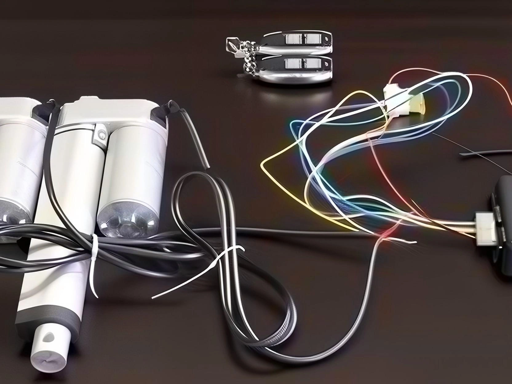
The five wires serve two distinct functions: two thick wires carry the high-current power needed to drive the motor, while three thinner wires carry the low-voltage feedback signals that indicate limit switch positions.
Wire Color Codes Explained
Understanding the wire color coding is essential for correct installation:
Wire Type
Color
Gauge
Function
Power (Positive)
Thick Red
14-16 AWG
Main power input (extend)
Power (Negative)
Thick Blue
14-16 AWG
Main power input (retract)
Upper Limit Signal
Thin Red
22-24 AWG
Signal at full extension
Lower Limit Signal
Thin Black
22-24 AWG
Signal at full retraction
Common Ground
Thin Green
22-24 AWG
Shared ground for feedback
The thick wires (red and blue) handle the motor current—typically 5-20 amps depending on the actuator model. Never use these thin signal wires for power delivery, as they will overheat and fail. The thin wires (red, black, and green) operate at low current (milliamps) and voltage (typically 5-12V DC) purely for signaling purposes.
Pre-Wiring Safety Checklist
Before beginning any wiring work, follow these essential safety precautions:
Disconnect power — Always disconnect the power source before wiring. Unplug the power supply or remove the battery connection.
Verify actuator specifications — Check your actuator’s voltage rating (12V or 24V are common) and current requirements. Matching voltage is critical.
Use appropriate gauge wire — Ensure power wires are appropriately sized for the current draw. For actuators drawing up to 10 amps, 16 AWG is minimum; for higher currents, use 14 AWG.
Keep signal wires separate — Route the thin signal wires separately from power wires to prevent electrical interference.
Step-by-Step Wiring Instructions
Step 1: Identify Your Wires
Locate the five wires extending from your actuator’s cable. Confirm which are the thick power wires versus the thin signal wires. The thick wires are typically red (positive) and blue (negative for retract), while the thin wires include red (upper limit), black (lower limit), and green (common ground).
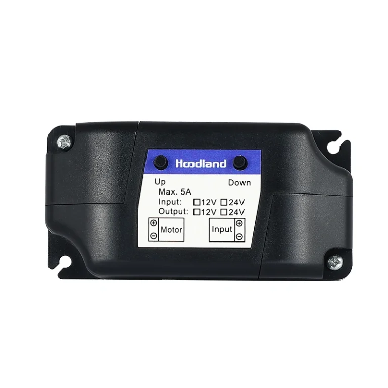
Step 2: Connect Power Wires
Connect the thick power wires to your power supply:
Thick Red Wire → Positive terminal of your power supply (this extends the actuator)
Thick Blue Wire → Negative terminal of your power supply (this retracts the actuator)
Note: Some manufacturers use different color coding. If your actuator doesn’t extend when power is applied, simply swap the connections—this reversing polarity won’t damage the motor.
Step 3: Connect Signal Feedback Wires
Connect the three thin signal wires to your controller or PLC inputs:
Thin Green (Common) → Connect to the ground or negative rail of your controller
Thin Red (Upper Limit) → Connect to a digital input that reads HIGH when extended
Thin Black (Lower Limit) → Connect to a digital input that reads HIGH when retracted
These switches close (complete the circuit) when the actuator reaches its limit positions, providing feedback to your control system about the actuator’s position.
Step 4: Test Your Wiring
Before finalizing installation, test the system:
Apply power to the actuator
Use your controller to extend the actuator fully—the thin red wire should signal when fully extended
Retract the actuator—the thin black wire should signal when fully retracted
Verify that limit signals are working correctly before mounting the actuator
Common Wiring Configurations
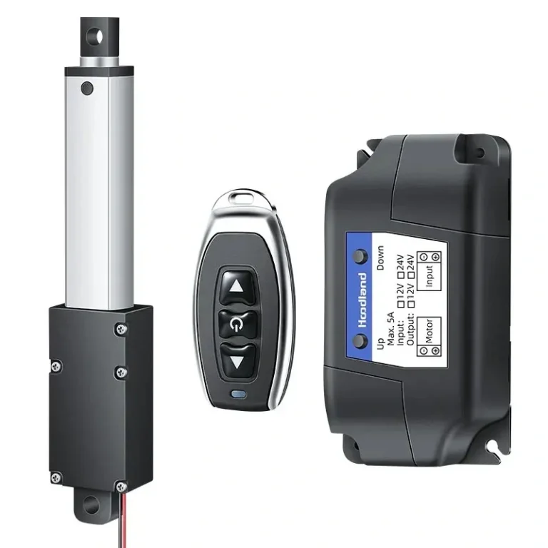
Direct Push Button Control
For simple manual control without automation, you can use two push buttons:
One button connects power to extend (red wire to positive)
Another button connects power to retract (blue wire to negative)
Indicator lights can be wired to the signal wires to show limit positions
Controller/PLC Integration
For automated systems, wire the signal wires to digital inputs on your controller:
Program your controller to read the upper limit signal as “extended”
Read the lower limit signal as “retracted”
Use these signals to prevent over-extension or to trigger other system actions
Troubleshooting Common Issues
Actuator Won’t Move
Check power connections — Verify thick red and blue wires are securely connected to the correct polarity
Test voltage at actuator — Use a multimeter to confirm proper voltage is reaching the actuator
Inspect for damage — Check the cable for cuts or crushed sections
No Limit Signal Feedback
Verify ground connection — The thin green wire must be properly connected to controller ground
Test with multimeter — Set to continuity mode and check if limit switches close at end positions
Check controller inputs — Ensure your controller inputs are configured correctly
Intermittent Operation
Check wire connections — Loose connections can cause intermittent operation
Reduce wire length — Long cable runs can cause voltage drop; use thicker gauge wire for longer runs
Separate signal and power wires — Keep signal wires away from motor cables to reduce interference
What is the difference between a 2-wire and a 5-wire linear actuator?
A 2-wire actuator only provides basic extension and retraction by reversing polarity. A 5-wire actuator includes three additional internal limit switch wires that provide feedback signals to a controller when the actuator reaches its end positions.
Can I run power through the thin feedback wires?
No. The thin wires (typically 22-24 AWG) are for low-current signals only. Running motor-level current through them will cause the wires to melt and damage the internal switches.
How do I know which wire is the common ground for feedback?
In most ActuLift 5-wire systems, the thin green wire is the common ground. You can verify this with a multimeter by checking for continuity between the green wire and the signal wires when the limit switches are triggered.
Do I need a controller to use a 5-wire actuator?
While you can move the actuator with just a power source, a controller or PLC is recommended to utilize the feedback wires for safety, automation, and precise position monitoring.
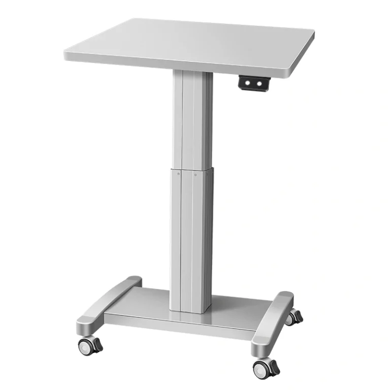
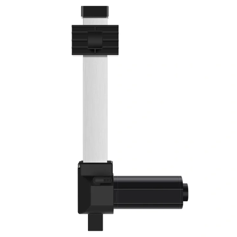
Choosing the Right Linear Actuator
If you’re selecting a linear actuator for your project, consider these options:
Ready to automate your project? Understanding how to properly wire a 5-wire linear actuator gives you the foundation to build reliable automated systems with precise position control.
Selecting the right electric linear actuator or lifting column is critical for your project's performance. As a professional Motion Control & Automation Manufacturer, our engineers help you customize load capacity, stroke length, and IP ratings based on your specific application. Share your technical requirements for a tailored solution.
ActuLift supports end-to-end customization, from structural design and stroke parameters to branding and casing finishes, helping you build a powerful brand identity.
Rapid Response & Prototyping
We understand the importance of speed in B2B procurement, utilizing optimized production workflows to ensure efficient responses from sample development to bulk delivery.
Stable Quality & Traceability
With ISO9001 quality assurance, every product—from material entry to final factory testing—is recorded in our electronic logs, ensuring high consistency in delivered goods.