ActuLift Custom OEM/ODM: From Concept to Production-Ready Actuators
Discover ActuLift’s comprehensive OEM/ODM capabilities for custom linear actuators. From 10-1000mm precision strokes to tailored mounting and cable options, learn how our engineering team transforms complex motion concepts into production-ready industrial solutions.
Use this guide to define an OEM/ODM linear-motion request around load, stroke, speed, duty cycle, mounting, cable routing, controls, environment and documentation before a configuration-specific review.
Table of Contents
Introduction: The OEM/ODM Challenge in Linear Actuation
OEM projects can differ in load, travel, mounting geometry, controls, cable routing, environment and documentation. The useful starting point is to define those requirements, then compare them with the closest existing actuator or lifting-column platform.
ActuLift’s OEM/ODM project workflow starts with requirement review. Dimensions, interfaces, controls or other changes are evaluated against the selected product family; feasibility, performance, documentation, tooling, validation and commercial terms must be confirmed for the specific project before approval.
Why Custom Linear Actuator Solutions Matter
Standard actuators come with fixed stroke lengths, predetermined mounting configurations, and preset cable lengths. While convenient, these standardized options frequently create challenges during integration:
Stroke limitations: Standard strokes may not reach required positions, causing operational gaps
Mounting incompatibilities: Existing hole patterns don’t align with actuator interfaces
ActuLift’s custom approach eliminates these friction points by delivering actuators designed specifically for your application from the start.
Stroke and Travel Requirements: Define Before Review
The stroke length defines how far your actuator can extend and retract—making it one of the most critical specifications for any application.
Stroke Range Overview
Stroke availability is product-family and configuration dependent. Define the required travel, retracted and extended length, mounting geometry, load, speed and stability constraints, then confirm the feasible range for the selected platform.
Stroke / package input
What to define
Required travel
Minimum and maximum motion needed by the mechanism
Retracted / extended length
Available installation envelope and end-clearance limits
Load and speed
Required working point through the intended travel
Geometry / stability
Mounting points, side-load risk, critical-speed or column-stability constraints
Benefits of Custom Stroke Engineering
When you specify your exact stroke requirements, you gain several advantages:
Travel fit: define the motion range required by the actual mechanism rather than choosing travel from a generic application label
Packaging fit: confirm retracted length, extended length, end dimensions and clearance in the assembly
Commercial fit: compare standard-platform and project-specific changes using the current quotation, tooling and validation scope
Integration fit: validate the selected sample against mounting, load path, controls and surrounding structure before release
Do not assume a particular stroke or positioning capability from this article. Submit the required travel and package constraints, then confirm what the selected actuator family can support.
Mounting Interface Requirements: Drawings First
Mounting configuration determines how the actuator connects to your equipment. Incompatible mounting interfaces create installation challenges, require custom brackets, or necessitate redesigns—all adding time and cost to your project.
Standard and Custom Mounting Options
For OEM review, define the mounting interface from the mechanism drawing, including thread or pin standard, interface dimensions, load direction, articulation and tolerance requirements:
Mounting inputs to define:
Threaded interfaces: specify thread standard, size, engagement, material and load direction
Assembly constraints: define access, fastener, rotation, alignment and service requirements
Custom Mounting Engineering
Project-specific mounting changes may be reviewed when the standard interface does not fit the mechanism. Treat the following as design inputs, not default available options:
Hole patterns: submit the required layout and tolerances for feasibility review
Flange interfaces: submit the mating geometry, load case and material/environment requirements
Pivot interfaces: define angular travel, pin loading, articulation and clearance
Rotating / trunnion-style interfaces: define the required motion and confirm whether the selected platform can support it
Submit a controlled interface drawing for engineering review. Any project-specific interface should be confirmed by drawing revision, sample fit check and the agreed acceptance criteria before production.
Cable, Connector and Routing Requirements
Cable length might seem minor, but improper sizing creates significant installation challenges. Too-short cables require extensions or rewiring; excessively long cables create routing clutter, potential pinch points, and unprofessional appearances.
Cable Customization Options
Cable and connector requirements should be defined as project inputs and confirmed for the selected actuator/controller configuration:
Length: specify required finished cable length, routing allowance and tolerance
Connector: specify mating connector, pinout, locking, sealing and service requirements
Conductor sizing: confirm current, voltage-drop, flexing, temperature and applicable wiring requirements
Cable construction: define flex, abrasion, chemical, temperature, shielding or environmental requirements as applicable
Installation Advantages
A configuration-specific cable plan can improve integration when it is designed and validated with the finished equipment:
Routing fit: define bend radius, strain relief, pinch-point avoidance and service access
Connection strategy: minimize unnecessary joints while meeting service and replacement needs
Packaging: confirm where excess cable, connectors and protective sleeves can be accommodated
Assembly method: confirm cable length, connector orientation and test method on the production assembly
Submit the cable/connector requirement with the mechanism and controller information; availability, tooling, pinout, sealing and validation requirements must be confirmed before it becomes an approved configuration.
12V requirement: confirm a compatible actuator, controller, current draw and wiring for the selected build
24V requirement: confirm a compatible actuator, controller, current draw and wiring for the selected build
Other supply requirements: submit the voltage and electrical architecture for feasibility review; do not assume availability
Force Ratings
Define the complete moving and holding load case, linkage geometry, duty cycle, speed and safety margin, then confirm the rated working point of the selected product family. Do not infer a universal custom-force range from this article.
Environmental Protection
Environment: define dust, water, contamination, temperature, cleaning and storage exposure
Target ingress protection: state the required IP condition and request configuration-specific test/documentation evidence; a target is not an automatic available rating
Corrosion / chemical exposure: define materials, coatings, salt/chemical exposure and lifecycle expectations for feasibility review
Speed Variations
Define the required speed at the expected load together with stroke, duty cycle, controller behavior and stopping requirements. Confirm the achievable working point for the selected configuration rather than assuming a custom speed is always available.
The Custom Actuator Process: From Inquiry to Delivery
1. Specification Review
Submit your requirements—stroke length, mounting configuration, cable length, voltage, force, and environmental specifications. ActuLift’s engineering team reviews each parameter for feasibility and optimization opportunities.
2. Engineering Consultation
Direct communication with ActuLift’s technical specialists ensures all considerations are addressed. Recommendations for optimization are provided based on application requirements.
3. Prototype Development
Where a sample or prototype stage is agreed, use it to verify fit, function and the defined performance criteria. Sampling supports validation but does not replace the buyer’s finished-system testing, qualification or regulatory responsibilities.
4. Production and Delivery
After the selected configuration, drawing revision, quality requirements, documentation package and commercial terms are agreed, production can proceed under the approved order. The applicable inspections, records and supplied documentation must be defined for that project rather than assumed from this article.
Applications Across Industries
OEM/ODM requests can come from different equipment sectors. The application label does not by itself establish actuator suitability; evaluate the selected linear actuator or lifting-column platform against the actual requirements:
Care-related / medical equipment: define finished-device load, controls, safety, cleaning, documentation and regulatory requirements; component customization does not establish medical suitability
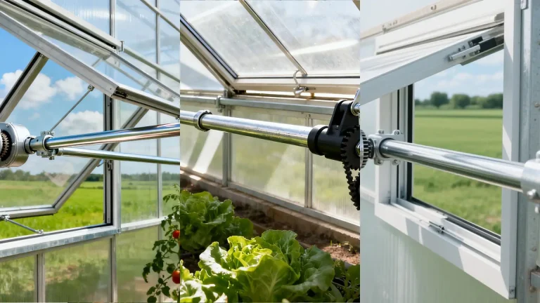
Agricultural machinery: define contamination, washdown, vibration, temperature, load and service conditions
Marine-adjacent / corrosive environments: define salt, moisture, materials, sealing and corrosion-test requirements; do not assume marine suitability
Vehicle / mobile equipment: define voltage, shock, vibration, temperature, mounting and applicable qualification requirements
What is the difference between OEM and ODM for linear actuators?
For this sourcing workflow, OEM generally starts from buyer-defined drawings or specifications, while ODM may involve more supplier-side engineering input from functional requirements. In either case, freeze the selected platform, controlled drawing, configuration, validation plan and commercial/documentation scope before production.
Can I request a custom IP rating for harsh environments?
You can submit a target ingress-protection requirement, but availability is product- and configuration-dependent. Define the actual dust/water exposure, mounting, cable/connector interfaces and cleaning conditions, then request configuration-specific test or declaration evidence before approval.
What is the typical lead time for a custom actuator prototype?
There is no universal prototype lead time. Timing depends on the selected base platform, engineering changes, drawings, tooling, components, sample quantity, test scope and documentation. Confirm the current project schedule in the quotation or project plan.
Do you support custom feedback signals like Hall sensors?
Feedback or control requirements such as Hall sensing, potentiometer, limit switching or other interfaces can be submitted for review, but availability and electrical details are configuration-specific. Synchronization or position-control performance must be validated with the selected actuator, controller, wiring and mechanism.
Conclusion: Partner with ActuLift for Your Custom Actuator Needs
OEM/ODM review should begin with a complete requirement set and the closest existing product platform. Any requested change to stroke, mounting, cable, controls, environment or other interfaces should be confirmed through the project-specific engineering and validation process.
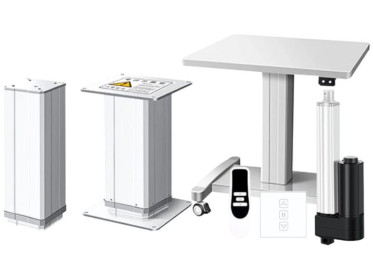
Start from the relevant linear actuator, lifting-column, control or mounting family, then document which dimensions, interfaces, controls or environmental requirements need configuration-specific review.
Ready to define an OEM/ODM request? Send the load, stroke, speed, duty cycle, voltage, controls/feedback, mounting drawing, cable/connector requirements, environment, documentation needs and target quantity for configuration review.
ActuLift Linear Actuator Families — start from the closest current platform, then use controlled drawings, approved specifications and configuration-specific test/documentation evidence for final decisions
Get Expert Insights on Industrial Motion Control
Selecting the right electric linear actuator or lifting column is critical for your project's performance. As a professional Motion Control & Automation Manufacturer, our engineers help you customize load capacity, stroke length, and IP ratings based on your specific application. Share your technical requirements for a tailored solution.
ActuLift supports end-to-end customization, from structural design and stroke parameters to branding and casing finishes, helping you build a powerful brand identity.
Rapid Response & Prototyping
We understand the importance of speed in B2B procurement, utilizing optimized production workflows to ensure efficient responses from sample development to bulk delivery.
Quality Documentation & Traceability
Quality and traceability requirements vary by project. Ask ActuLift for the applicable inspection records, product specifications, drawings and available compliance documentation for the selected model and order.